Slewing Bearing Installation Surface

Mechanical machining of the bearing connection surfaces on the connecting structure is required . The mounting position of slewing bearings must correspond to that shown in the drawing. If a transporting cross was delivered, it has to be removed before installation.

The corrosion protection can be removed with an alkaline cleaner. Cleaner must be prevented from coming into contact with the seals or the raceway. Remove the protective coating from the upper and the lower mounting surfaces of the slewing bearing as well as from the gear.

The corrosion protection can easily be removed, for example, using a biodegradable alkaline cleaner.

Rapid removal of the corrosion protection and low environmental impact.

The unhardened zone between the beginning and the end of the hardened region of the raceway is marked with an “S” on the inner or outer diameter of each bearing ring. On the gear ring, the hardness gap is marked on the axial surface. Wherever possible, the hardness gap “S” must be positioned outside the main load-carrying areas. If the main working area for the application is known, then the hardness gap of the ring loaded on the circum-ference must also be positioned outside the main load-carrying area.

The bearing must be completely screwed on for commissionings and test runs. Sufficient load / moment loan must be applied to avoid a slip-stick effect on the anti-friction bearing bodies.

Gearing

Entanglement hazard due to exposed gear

  • Keep hands away from moving parts

The backlash is adjusted relative to the three gear teeth marked in green and should be 0.03 – 0.04 x module.After the final tightening of the bearing,the backlash should be rechecked over the entire circumference. A tip edge radius and a tip relief must be provided on the pinion.

What is the reason for the high noise of spur gear drive?

In addition to running accuracy, load capacity and fatigue life, noise is also an important indicator of the performance of a spur gear drive. Noise not only affects the operating environment of the equipment, but also affects the gear transmission accuracy and the overall operation and transmission of spur gear drives. With the successive issuance of ISO14000 and ISO18000 standards, controlling its transmission noise becomes more and more important.

The reason for the high noise of spur gear drive

SG-I Spur Gear Slewing Drive

1. Influence of gear accuracy: Gear accuracy is often designed with economic benefits as the basis, ignoring the impact of accuracy on drive noise and backlash. When the gear accuracy cannot be reached, it will increase the operating noise.

2. Influence of gear width: Under the condition of constant torque, the noise curve gradient of large tooth width is lower than that of small tooth width, and the noise of small tooth width is relatively large.

3. Influence of tooth pitch and pressure angle: Small tooth pitch can contact more gears at the same time, the overlap of gears increases, and the noise is larger.

4. Influence of gear displacement coefficient: When the gear transmission performance is improved, the bearing capacity, the displacement coefficient, the central moment, etc. are not suitable for operation, it is easy to generate noise.

5. Speed ​​control: The noise of the spur gear drive is also different at different speeds. With the increase of the speed, the noise of the drive will also increase.

6. Influence of dynamic balance: Misalignment of assembly will lead to unbalanced operation of the shaft system, and in the state of semi-loose and semi-tight gear meshing, it will lead to aggravation of driving noise, and unbalanced gear assembly will affect the accuracy of the transmission system.

7. Loose or damaged parts: Looseness of individual parts during installation will lead to inaccurate positioning of the system, and abnormal meshing will cause shaft movement to generate vibration and noise. Damage to the transmission parts will also lead to inaccurate or unstable movement of the system, resulting in unbalanced moving parts and vibration and noise during high-speed movement.

8. Improper use or maintenance: Dirty impurities enter the drive and cause wear and tear, causing malfunction noise or improper lubrication, causing wear and tear to increase noise. After understanding why the spur gear drive is noisy, let’s take a look at the specific solutions.

Spur gear drive operation noise solution

SG-M Spur Gear Slewing Drive

1. Improve the precision of the drive gear and reduce the transmission error and equipment noise. Control tooth profile error. Reducing the roughness of the tooth surface can reduce the noise emission.

2. When the drive transmission space allows, increase the gear width, reduce the unit load under constant torque, reduce gear winding and reduce noise excitation, while increasing the gear width can also increase the bearing capacity of the gear and improve the bearing torque of the reducer .

3. The correct and reasonable selection of the displacement coefficient can not only make up for the central moment, avoid gear undercut, ensure that the concentric condition is met, improve the transmission performance of the gear, increase its bearing capacity and the service life of the gear, and control the operating noise.

4. Increase the hardness of the spur gear drive gear tooth surface. The high hardness of the gear tooth surface can reduce the possibility of gear deformation, and at the same time, it has a certain effect on reducing the driving noise.

5. Do a good job of shock absorption between the equipment and the drive to avoid resonance and noise between the fuselage and the foundation support and connecting parts. High toughness, high damping base materials can be selected to reduce noise and vibration.

6. Regularly repair the equipment, tighten the parts, find and repair the faulty parts in time, and replace the parts that cannot be repaired in time to stabilize the equipment and reduce the noise level.

7. Supplement lubricating oil in time, choose suitable lubricating oil, avoid equipment heating, wear and other failures caused by insufficient lubrication, and cause failure problems such as increased noise.

8. Keep the internal parts of the drive clean and prevent impurities from entering the spur gear drive and affecting the normal operation of the transmission system.

The above is all about the reasons for the loud operating noise of the spur gear reducer, and also includes specific solutions. There may be many reasons for the noise during the operation of the reducer. It should be noted that the influence of various aspects of the rotary reducer is from Reduce the impact of noise in many ways.

How is the spur gear drive packaged? Packaging method and function

Spur gear drive, as a general-purpose reducer that integrates the functions of rotation, deceleration, and drive, can use the transmission structure to achieve a transmission with a large transmission ratio, which reduces the failure rate of the host to a certain extent. It is usually modular and highly integrated. After the assembly is completed, special attention should be paid to storage and transportation of this device to avoid impacts or other conditions that affect its function. For this reason, the product should be packaged.

How is the spur gear drive packaged

1. Packaging method

(1) Cleaning and assembly: clean each part after passing the inspection to remove dirt and impurities on the surface, and then assemble the parts and assemble them into a complete rotary drive.

(2) Lubrication: Inject grease into the rotary drive through the oil injection hole, and wipe the surface after the entire rotary drive is qualified to ensure the smoothness of the surface.

(3) Anti-rust: Paint anti-rust oil on the outer surface of the slewing drive, especially the slewing bearing as the main transmission component, should be fully lubricated and anti-rust work to prevent rust during storage or transportation. Of course, during the production process, the manufacturer will also spray and other special anti-rust treatments on the spur drive housing. After the anti-rust oil is applied, it should be packed in time to isolate the air to achieve a better anti-rust effect.

(4) Outer packaging: put the packed straight gear reducer in a wooden box, pay attention to the protection of the inner wall of the wooden box, generally put a layer of pearl cotton on the bottom of the box to prevent the rotary drive from scratching in the wooden box, and use pearl cotton around Separate the wooden box from the drive and try to fill the gap to avoid shaking and bumping during transportation. If you want to stack it, you need to use a wooden strip to isolate and support between the two rotary drives to prevent the upper product from compressing the lower product. In addition, the upper layer of the wooden box should be laid with pearl cotton to prevent the product from being scratched when the lid is opened and nailed. At the same time, fix the outer packaging and prevent moisture.

Spur Gear Drive

2. Matters needing attention

(1) Choose suitable lubricating grease and anti-rust oil according to the characteristics of the product. It should be appropriate, not too much or too little.

(2) Avoid stacking multiple products if possible, and protect a single product to avoid damage such as stacking collisions, extrusion deformation, etc.

(3) A suitable packing box should be customized according to the size of the product, which can greatly reduce the damage caused by extrusion or shaking due to the mismatch of the box and the product. At the same time, pay attention to whether the packing box is strong.

(4) During the transportation process, attention should be paid to moisture-proof and stable transportation, to avoid the impact of external environment such as bumping into water.

Slewing Drive

The role of spur gear drive packaging

1. Product protection: Tight packaging can better protect the products. The spur gear drives produced are all qualified products that have been inspected. However, if they are transported or stored, they will inevitably experience some violent transportation or accidents. If the packaging is not In place, it may cause damage to the product. In order to deliver the product to the customer intact, tight packaging is necessary.

2. Convenient storage: Sometimes customers don’t use the spur gear drive immediately after purchasing it, and may need to be stored for a period of time, so the anti-rust treatment of the product packaging box is particularly important.

3. Transportation protection: It is inevitable that the product will be directly loaded and unloaded by forklift during transportation, and bumps will inevitably occur. The use of strong outer packaging can play a certain protective effect and play a pre-protective role against some uncontrollable conditions during transportation.

4. Manufacturer’s information display: The outer packaging is not only to protect the product but also to display the company’s image. Good standardized packaging reflects the manufacturer’s standardized production and good production management system, and is also a display of the manufacturer’s strength. At the same time, product information such as the product model, inspection certificate, and instructions for use will also be displayed on the outer packaging, so that the process of receiving and transportation can be more clearly and intuitively distinguished.

What is the installation process of spur gear drive?

Slewing drive is divided into spur gear slewing drive and worm gear slewing drive. Spur gear slewing drive is also called spur gear drive, gear slewing drive, and gear slewing reducer. Its main applications include solar and wind power generation equipment, robots, radar, low-speed heavy-duty lifting, lifting equipment, precision CNC turntables and other products.

Application principle of spur gear drive

Spur gear drive is a full-circle reduction transmission mechanism that inherits the driving power source. Its working principle is to use all levels of gear transmission to achieve the purpose of speed reduction. The spur gear slewing drive uses a slewing ring as a drive follower and a mechanism attachment. By attaching a driving part and a driving source to one of the inner and outer rings of the slewing ring And the cover, and the other ring is used as the driving follower and the connecting base of the driven working part. In this way, the slewing bearing itself is a full-circle slewing connector, and the driving power source and main transmission parts are configured. Rotary drive is such a general-purpose reduction transmission mechanism that integrates the functions of rotation, speed reduction and driving.

Installation method of spur gear drive

1. Open the package of the slewing drive, check the certificate and label, and confirm that the type of slewing drive used is correct.

2. Make sure to install under no-load conditions, and level the installation position after keeping the surface of the equipment clean.

3. After leveling, install the rotary drive on the equipment support using a wrench, and level the equipment again. The circumferential flatness error can only have one wave ups and downs within any range of 180 degrees, and the change is gentle.

4. Position the equipment and place the soft belts on the inner and outer ring raceways of the slewing drive on both sides of the main load plane. That is 90 degrees staggered from the main load zone. There is a blockage or “S” mark on the soft belt.

5. Tighten up after positioning, use a feeler gauge to measure the fit between the rotary drive and the mounting surface. If the fit is not good, fill it with appropriate materials.

6. Adjust the gear backlash. Use a feeler gauge to measure and adjust the gear radial runout point. If the backlash is not within the specified value, move the pinion to change the center distance, and mark the gear radial runout point in the tooth groove with green paint. .

7. After installation, lubricate the supporting slewing drive, including raceways and gears. In order to ensure sufficient lubrication, the grease specified in the drawing or product instruction manual should be refilled before the first use.

Installation precautions

1. Before installation, confirm whether the motor and gear slewing drive are intact, and check whether the dimensions of the parts connected to the slewing drive match.

2. Screw on the screw on the dust-proof hole on the outside of the rotary drive flange, adjust the PCS system clamping ring to align the side hole with the dust-proof hole, and insert the inner hexagon to tighten. Then remove the motor shaft key.

3. Before installation, wipe the motor input shaft, positioning boss and the anti-rust oil at the connecting part of the speed reducer with gasoline or zinc-sodium water.

4. After the rotary drive is installed, it can be turned by hand, and the application is flexible without jamming. Before starting the machine, fix the connecting screws. The no-load test run should be no less than 2 hours, and the operation should be stable, without impact, vibration, noise and oil leakage. If found, it should be eliminated in time. When using, check whether the fasteners are loose. Ensure normal operation.

5. Naturally connect the motor and the reducer. When connecting, it must be ensured that the output shaft of the reducer and the input shaft of the motor are concentric, and the outer flanges of the two are parallel, so as to extend the service life and obtain the ideal transmission efficiency and comparison. Low noise. In addition, do not hit with a hammer during installation to prevent excessive axial or radial force from damaging the bearings or gears. Be sure to tighten the mounting bolts before tightening the tightening bolts.

The above is the whole content of the spur gear drive application principle, installation method and precautions. Spur gear drives can be used in fields that require high precision such as CNC machine tools and military radars. If you have any questions during the installation or use of the spur gear drive, please call for consultation or leave a message.

What are the self-locking methods of spur gear drive?

Spur gear drive is also a kind of gear type slewing drive. Its transmission principle is a device in which the pinion drives the gear ring of the slewing ring to rotate and reduce. From the deceleration principle of the slewing drive, we can find that it does not have the self-locking function. Yes, if you want to achieve exact stop, you need to use a brake device for locking. The editor of Ronda will introduce to you the self-locking methods of spur gear drive.

What is spur gear drive self-locking

Spur gear drive self-locking is to manually stop the drive when it needs to be stopped. The main use of the self-locking principle is that when the transmission angle, that is, the complementary angle of the pressure angle, is less than one-half of the friction angle, the conditions for self-locking can be achieved. That is to follow the self-locking phenomenon, when the resultant force of the transmission force of the object acts within the friction angle, no matter how great the force is, there will always be a total reaction force to balance it and keep the object still. However, the spur gear drive cannot achieve self-locking and needs to rely on external force to complete the drive locking effect. The following specifically introduces the ways to realize the self-locking of the spur gear drive.

Self-locking method of spur gear drive

VE Series Slewing Drive


1. Servo motor self-locking

When the spur gear slewing drive is driven by a servo motor, when the driving force is small inertia, that is, the starting is frequent and the load is small, the servo motor is usually stopped to achieve the locking of the spur gear drive. The locking force of the servo motor is passed The reduction ratio of the spur gear drive is amplified, and then reflected on the turntable to achieve drive locking. At this time, the locking force is relatively large, which is very suitable for working conditions with small inertia.

2. Self-locking hydraulic motor

The spur gear drive using hydraulic motor can be braked by the hydraulic motor during use, so as to realize the locking of the spur gear drive. Among them, the hydraulic motor braking method is divided into the following three types:

(1) Braking with overflow valve: It can realize bidirectional braking to the hydraulic motor, and can play a buffering effect.

(2) Braking with accumulator: Install accumulators near the oil inlet and outlet of the hydraulic motor to achieve bidirectional braking on the hydraulic motor.

(3) Braking with normally closed brake: When the hydraulic oil in the brake hydraulic cylinder loses pressure, the brake will act immediately to achieve braking.

SDE-PDE SERIES SLEWING DRIVE

3. Self-locking brake reducer

The disc brake that uses the spur gear of the brake reducer to drive the brake motor is installed on the end cover of the motor’s non-output end. When the brake motor is connected to the power supply, the electromagnet attracts the armature and the brake armature is separated from the brake disc and the motor starts When the brake motor loses current, the electromagnet cannot attract the armature, the armature falls back to the brake disc, and the motor stops rotating. The self-locking effect of the spur gear drive is realized through the characteristics of the brake motor’s power-off braking.

4. Bolt brake

What are the self-locking methods of spur gear drive? You can also install a pin hole on the gear drive to lock the spur gear drive that requires a fixed position. At the beginning of the design, a pin hole is designed on the rotating ferrule, and a starter or hydraulic pin device is designed on the frame. During the driving process, the bolt mechanism can pull out the pin to allow the drive to rotate normally. Insert the pin back into the bolt hole at the position where it needs to be stopped and fixed. The drive is fixed on the frame by the pin of the ferrule and cannot rotate. Realize self-locking.

5. Self-locking brake gear

A separate brake gear is installed on the rotary drive. This method is suitable for situations where frequent braking is required and the spur gear drive power is large and the braking power is large. Large braking force will cause the failure of the connection between gears, reduction gears, and motors, and shorten the service life of the spur gear drive. For this reason, the spur gear drive with independent brake gears can be used to achieve separate braking to avoid the transmission force. The connecting parts fail due to the sudden braking, and the parts are damaged.

The above is the main introduction about the self-locking methods of the spur gear drive. The realization of the self-locking function of the slewing drive can be selected according to the specific equipment operating conditions and requirements.

What should I do if the spur gear slewing drive shakes? Shaking causes and solutions

Spur gear slewing drive may encounter various problems during use. Generally, it can be used after adjustment. Shaking is also one of the common problems among many problems. Shaking during drive operation may affect the overall stability of the equipment. What should I do if the spur gear slewing drive shakes? Let’s work with the spur gear drive manufacturer to understand the reasons and solutions for the shaking of the spur gear rotation drive.

Causes of shaking of spur gear slewing drive

Customized Product

1. Excessive bearing wear: The bearing has been working for a long time, and the bearing gap will be too large or unbalanced, which will cause the bearing to generate heat and friction. The rotor and the stator will be afraid of friction, which will directly damage the bearing. The sliding bearings are prone to vibration, because the viscous effect of the lubricating oil will cause the shaft to float, and this can also be related to the weight of the bearing. If the weight of the bearing is larger, the wear will be faster.

2. High vibration of the frame: In some cases, excessive vibration of the frame may also have an impact. The vibration frequency of the frame can be said to be the rotation speed of the spur gear. It may be a problem with the frame design, which may cause an unstable state in operation.

3. Rotor mechanical imbalance: The imbalance mentioned here refers to the imbalance of the rotor in a static state and the imbalance in the case of rotation. The rotor deviates from the axis and deflection occurs under the action of centrifugal force, resulting in abnormal vibration.

4. Rotor parts are loose: several parts of the motor rotor: commutator, magnetic poles, belt pulleys, etc., these looseness will also occur when the spur gear rotary drive is used for a long time. Generally, in this case, the rotor will have noises, and these situations will occur. It should be dealt with as soon as possible, because the consequences will become more and more serious over time.

5. Leakage of the drive joint surface: Leakage on the joint surface of the reducer will cause oil shortage, oil cut, and increased wear of the gear meshing surface, shaking, and even seizure welding or breakage may occur in severe cases, resulting in equipment accidents.

6. Drive out of adjustment: When the calibration line between the motor and the driver in the gear reducer is not good, and vibration is prone to occur, adjust the calibration line and reinstall the connection between the driver and the motor, so as to stabilize the rotation of the motor bearing.

7. Rotor mechanical imbalance: The imbalance mentioned here refers to the imbalance of the rotor in a static state and the imbalance in the case of rotation. The rotor deviates from the shaft center and deflection occurs under the action of centrifugal force to produce abnormal vibration.

SDE-PDE Series Slewing Drive

The spur gear rotation drive shaking solution

1. Bearing wear may need to be filled with lubricating oil and continue to be used according to the wear condition, or choose to replace the bearing when the wear is severe.

2. The vibration of the bearing frame may be a problem in the design of the slewing drive, because the vibration frequency of the base is basically the same as the rotational frequency of the bearing. Design problems can be adjusted and resolved by contacting the manufacturer’s after-sales service. For example, product design problems within the warranty period can require the replacement of machinery and equipment. The straight-tooth drive produced by our Luoyang Longda Bearing has been researched and optimized for a long time, and the structure and product quality of the product design are reliable.

3. If the transmission is out of adjustment, adjust the calibration line and reinstall the connection between the driver and the motor, so that the rotation of the motor bearing can be stabilized.

4. The mechanical imbalance of the rotor may be due to the deviation of the rotor from the axis. The position of the rotor can be readjusted, or the design of the base can be considered. Generally speaking, the base can absorb the shock or vibration of the equipment and has a certain adhesive force. If it recurs after adjustment, only replace the base.

5. The sealing gasket can be replaced or the sealant can be applied to solve the shaking problem caused by leakage of the joint surface.

The above are the specific reasons and solutions for the shaking of the spur gear slewing drive. I hope to help you. In addition, if you have other questions when using the spur gear slewing drive, you are welcome to inquire us at Luoyang Longda Bearing Co., Ltd. We have many years of experience. The production experience of slewing reducer, slewing ring, spur gear slewing drive, if you have any needs, please feel free to inquire.

What are the installation methods of the spur gear slewing drive? And installation precautions

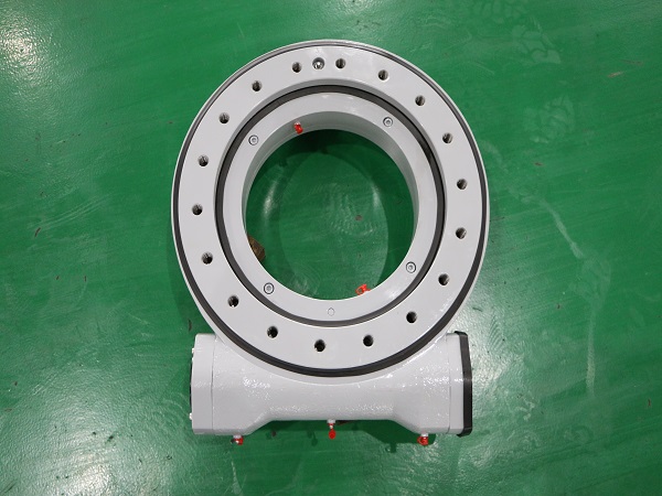
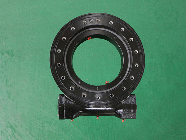
Spur gear slewing drive is a rotary drive. Due to the different types of drive teeth, it can be divided into straight-tooth rotary drive and helical-tooth drive, both of which are full-circle rotary drive reduction transmission mechanisms that inherit the driving power source. The previous article has already introduced the difference between the spur gear drive and the slew drive. I will not introduce it in detail here. Today, the Lunda bearing manufacturer will give a brief introduction on the installation methods of the spur gear drive. I hope it will be helpful to everyone.

Installation method of spur gear drive

1. Fixed installation with solid shaft

This installation method is to connect the output shaft driven by the spur gear with the metallurgical machinery through couplings, sprockets, gears, pulleys, etc., and the spur gear drives the bottom anchor bolts to firmly install the spur gear drive on the structure On a solid, vibration-free foundation. At present, most spur gear drives can adopt this installation method.

For large spur gear drives, threaded holes should be machined on the body feet to adjust the installation position with adjusting bolts; for the spur gear drive of the luffing mechanism, pins should also be used for locking to prevent movement during installation .

2. Single-point floating installation of hollow shaft

This installation method uses the output shaft driven by the spur gear as a hollow shaft and is connected to the transmission shaft of the working machine through an expansion sleeve. The entire driving device, including the motor, coupling, brake, and reducer, is installed on the support of the transmission device. Seat, and then supported by a ball hinge or bearing.
The installation principle is that the bearing point of the spherical hinge deviates from the center of gravity of the transmission device by a certain distance. In the working state, the bending moment caused by the eccentricity of the support point can be balanced with the bending moment caused by the load of the driving device. Therefore, the transmission shaft is not affected by the theory. Additional force.

3. Hollow shaft suspension installation

In this installation method, the output shaft driven by the spur gear and the metallurgical machinery shaft are connected by an expansion sleeve, and the support is completed by the output shaft and another torsion rod. This installation method is relatively simple, saves floor space, and can reduce the weight of the whole machine, and is suitable for transmission devices that transmit power from a vertical direction.

Spur gear drive installation is a delicate and complex task with high technical requirements. The operating procedures and design data must be strictly observed during operation. The general installation sequence is: equipment leveling and alignment, cleaning and assembly, adjustment and trial operation.

After understanding the installation methods of spur gear drives, the spur gear drive manufacturers will introduce some precautions in the installation of spur gear drives. I hope it will be helpful to everyone.

Precautions for installation of spur gear drive

WE Series Slewing Drive

1. Cleaning and inspection: clean the spur gear drive installation shaft before installation and use, and check whether the installation shaft is bruised or dirty. When the spur gear drive is installed in an inclined manner, ensure that the high position of the gear shaft bearing is lubricated by the gear oil in the box, and ensure that the gas in the box can be discharged from the high position of the box.

2. Keep the mating interface flat: When assembling the spur gear drive with the actuator and the prime mover, the connecting flange should be cleaned and polished to ensure the flatness of the connecting part of the connecting flange, to ensure that it is flush, and all bolts on the flange circumference should be matched. , Fastening.

3. Keep balance: The assembled transmission components (couplings, sprocket) should be kept in rotation balance, so as not to cause impermissible radial force or axial force. The internal thread of the assembly fixture and the shaft end is usually used, and the transmission part is pressed in with a bolt, otherwise it may cause damage to the internal parts of the spur gear drive.

4. Do a good job of leveling: The spur gear drive installation must be rigidly fixed on a solid horizontal foundation or a vertical frame, and the leveling must be done. It is necessary to ensure that the coaxiality of the prime mover, coupling, spur gear drive, and actuator is consistent, so as to avoid additional stress on the input and output shafts and bearings of the equipment and cause damage to the equipment input and output shafts and bearings.

5. Control the shaft gap: the coaxiality of the two connected shaft extensions should be controlled within the range of φ0.1mm, and there should be a gap of 2-8mm between the end faces of the two shaft extensions. The value of the gap depends on the specific equipment connected to the spur gear drive. Depending on the situation, it is necessary to ensure sufficient load transfer capacity and to ensure that the bearings driven by the spur gear are not subject to additional axial force.

6. Add gear oil: The grade of oil should be the spur gear drive value, or the oil equivalent to the oil should be used. And the amount of oil must be correct, and each spur gear drive has a sign with the grade and quantity of oil attached. The oil mirror is a display mirror of the oil level driven by the spur gear. On the side of the spur gear drive, the oil level should reach the upper and lower positions of the middle of the oil mirror when filling oil.

Spur gear drive lubrication and oil injection method

The lubrication effect has a great influence on the spur gear drive. If the lubrication conditions are not good, the heat generated by the spur gear drive will increase and its carrying capacity will decrease. Therefore, the lubricating oil and the amount of oil must be selected correctly to effectively ensure the normal operation of the spur gear drive transmission and prolong its service life.

Under normal circumstances, the lubrication method adopts oil pool lubrication and natural cooling; and for high-power spur gear drive or insufficient thermal power, pressure circulating oil lubrication or additional cooling devices can be used for cooling.

Under normal operating conditions, when the ambient temperature is (0~35)℃, or using circulating oil lubrication, choose medium-duty industrial gear oil 220#; when the ambient temperature is (35~50)℃, it is recommended to select medium-load Industrial gear oil 320#. In addition, the spur gear drive should be replaced with lubricating oil after the first 400 hours of operation.

What are the installation methods of spur gear drive? I believe you already know it. During installation, you can choose a suitable installation method according to the specific conditions of the machine to which the spur gear drive is adapted. Of course, some precautions during the installation process have been introduced by the spur gear drive manufacturer. Up. In addition, if you have any questions about the installation or use of other spur gear drives, you can call us Longda Bearings, and welcome your calls.