LDB improving reliability with Life Cycle Management

Improving reliability with Life Cycle Management
Install and commission Operate and monitor Maintain and repair Specification De sign and develop Manufacture
From specification and design to maintenance and repair, at LDB we use our Life Cycle Management approach to optimize both slewing bearing performance and service life while reducing total cost of ownership.
Specification Design and develop Manufacture and test Install and commission Operate and monitor Maintain and repair.

Specification
With in-house specialists across a wide range of critical areas such as seals, lubrication,
wear protection and more, LDB enables you to work with application engineers and designers to find the right solution, right from the start. We can support your project by combining all of this application knowledge to improve designs and enhance performance of your slewing bearing solutions.

Design and develop
With over 20 years of slewing bearing experience and unmatched engineering expertise, we can help you design and develop high-performance slewing bearings from 0,1 m to 18 m (> 8 m to 18 m are segmented). Our Engineering Consultancy Services (ECS) can provide advanced calculations and simulations utilizing high-tech computer programmes to optimize and verify designs. All of these advantages combine to improve operational performance of application machinery and reduce total cost of ownership.

Manufacture and test
we offer fast, local access to LDB technologies,services and support. Our extensive logistics network provides excellent availability of LDB’s slewing bearing solutions.
To be able to offer slewing bearing manufacturing and testing excellence, LDB has developed close relationships with certifying authorities. Upon request, these authorities can certify the design of your slewing bearing solutions and witness testing. While individual divisions have been approved for quality certification in accordance with ISO 9001 and other customer specific requirements.

Install and commission
LDB Life Cycle Management features a range of expert services, training and products to provide timely, accurate commissioning of new and replacement machinery. Our offers include flatness measuring and machining of slewing bearing seatings or resin grout installation for larger slewing bearings.

Operate and monitor
By collecting and analyzing the correct operating data, LDB can help you identify the need for machinery maintenance activities. We can help protect your slewing bearing solutions against unexpected failures and costly downtime with grease and oil analysis, wear surement,
vibration monitoring and ultrasonic inspection of the bearing’s structural integrity.

Maintain and repair
LDB maintenance and remanufacturing services include everything from inspection to complete restoration to the full working specifications of slewing bearings, by using adapted and controlled processes to extend the service life of the slewing bearing.

Slewing driver application

slewing bearing solutions and services

LDB slewing bearing solutions and services Optimize performance and service life

For more than 20 years, LDB has been designing and manufacturing many types and sizes of igh-performance slewing bearings to meet the specific needs of customers worldwide. Combining decadesof application knowledge, unmatched manufacturing expertise and our Life Cycle Management approach, LDB provides customized slewing bearings with outer diameters from 0,1 m to 18 m (>8 m to 18 m are segmented).

Unlike other providers of slewing bearings,LDB can offer fully tailored slewing bearing solutions with integrated advanced monitoring,lubrication and sealing systems for higher reliability and longer service life. Our wide range of expert slewing bearing services also help cut costs and optimize performance, while our global presence allows slewing bearing solutions and services to be delivered quickly around the world.

LDB Slewing bearing

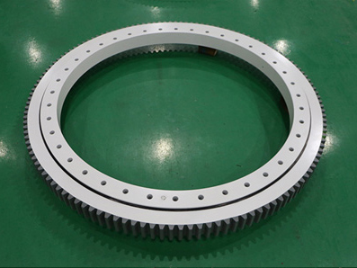
LDB Slewing bearing is a kind of rotating rolling element bearing or sliding bearing, which usually supports heavy but slowly rotating or swinging load. It is usually a horizontal platform, such as the windward platform of traditional crane, slewing stacker or horizontal shaft windmill.

Slewing bearing
Compared with other rolling element bearings, the section of slewing bearing is thinner, and the diameter is usually one meter or more.
LDB slewing ring is usually made of gear teeth integrated with the inner ring or outer ring, which is used to drive the platform relative to the base.
As a professional slewing ring supplier, we provide high-performance small and large slewing rings.

Slewing Driver Application

Slewing reducer -Slewing driver can be applied to the host of the circular motion, such as the crane rotation platform and the rotation machinery, etc. The turbine and worm mechanisms are often used for two -axis intertwined, large transmission ratio, small transmission power, or intermittent work. This product can be widely used in the field of engineering machinery represented by high -altitude operating vehicles, car cranes, new energy fields represented by solar photovoltaic power generation, wind power generation, and other fields of automation, machine tool manufacturing, aerospace communications and other fields. Therefore, the product’s market potential is huge.

Slewing drive
Slewing reducer –Slewing driver Subjective list

Rotate machine with a dual snail turn drive drive

Driver driver with a car

Heavy tablet transport vehicle turning driver

High -altitude operating vehicle turning driver

Railway turning driver Driven driver

Slewing claws with rotation driver

Bridge detection vehicle rotation driver device

China Railway Liangji Slewing Driver Device

Solar turning driver

Wind Turbine Bearings Market

According to the 2022 “Wind Turbine Bearings Market” research report, investment in the wind bearing industry is moving towards high quality, high quality and process, focusing on the development of unique wind turbines, and construction begins on the sea and the sea.

wind-bearings
Bearings in wind turbines have different designs, the most common design combination of CRB\TRB and rolling bearings, to meet different market needs.
In the application of wind turbine bearings, one of the selected bearings is a larger bearing, which has a longer service life and greater friction, which reduces the power generation efficiency of the turbine. Bearings currently in use are too costly to replace, and we need to be stronger than today’s bearing technology and stronger and more durable than existing materials.slewing berarings
Bearings of wind turbines are the focus of this research. When the bearing is working, it must bear the pressure in the movement, and can maintain a good internal movement effect.
According to the survey, the new wind turbine bearings are stronger and more efficient. The global wind turbine bearing market is expected to reach USD 9.6 billion in 2024. The next generation of wind turbines is cheaper, more powerful, and lasts longer. The widespread use of new bearings makes turbine equipment an optimal choice for renewable energy generation.

¿Cómo se fabrica la correa blanda para cojinetes de giro? La posición de instalación de la correa flexible.

La pista de rodadura del cojinete de giro generalmente necesita un tratamiento térmico. En el proceso de tratamiento térmico, debido a que el diámetro del círculo de la pista de rodadura del cojinete de giro es relativamente grande, generalmente se usa el enfriamiento de la superficie de la llama. El método consiste en usar acetileno para calentar la superficie de la pieza de trabajo que se va a endurecer y luego agregar agua para enfriarla. , este proceso se completa continuamente.

1. ¿Cómo se fabrica la correa blanda para cojinete de giro?

Durante la producción y el procesamiento del cojinete de giro, la pista de rodadura del dispositivo generalmente necesita un tratamiento térmico. Los procesos habituales son: forjado → mecanizado en bruto → tratamiento de templado y revenido → acabado → superficie de la pista de rodadura templado de la superficie de la llama → rectificado de la superficie de la pista de rodadura y otros procesos. Una de las superficies de la pista de rodadura se apaga con llama para formar una banda blanda.

El llamado cinturón blando es el área que no ha sido tratada térmicamente. La formación de la banda blanda es necesaria para el proceso de tratamiento térmico. En el proceso de tratamiento térmico de la corona de giro, debido a que el diámetro del círculo de la pista de rodadura de la corona de giro es relativamente grande, generalmente se utiliza el enfriamiento rápido de la superficie de la llama. El método consiste en usar acetileno para calentar la superficie de la pieza de trabajo que se va a endurecer y luego agregar agua para enfriarla.

Slewing Bearings

La pistola rociadora de llama calentada y la pistola de agua se montan juntas mientras realizan un movimiento circular a lo largo del círculo de la pieza de trabajo. Cuando el movimiento está cerca de los 360 grados, el calentamiento y el rociado de agua se detienen inmediatamente. Es decir, las áreas circulares de calentamiento y rociado de agua no se superponen. Pueden producirse grietas en la pieza de trabajo si las áreas del círculo donde se produce el calentamiento y el rociado de agua se superponen (tratamiento térmico en un ángulo superior a 360 grados en el círculo). El ancho tangencial del área no calentada es típicamente de 15 mm. Esta área de 15 mm se denomina correa blanda en el cojinete de giro, es decir, la denominada correa blanda es el área sin tratamiento térmico. La formación de la banda blanda es esencial para el proceso de tratamiento térmico.
​​
En circunstancias normales, el carácter de acero “S” está marcado en la posición donde se encuentra la correa blanda en la pieza de trabajo para indicar la posición específica de la correa blanda. La posición de instalación de la correa blanda es esencialmente para mejorar la vida útil del rodamiento. Desde la perspectiva del usuario y del fabricante, sigue siendo una posición razonable para instalar las correas blandas de los anillos superior e inferior del cojinete de giro. Por lo tanto, el fabricante del cojinete de giro debe marcar con precisión la posición de la correa suave del cojinete de giro, y el fabricante y el instalador deben instalar razonablemente la posición de la correa suave del cojinete de giro según sea necesario.

2. La posición de instalación del cinturón suave.

Slewing Bearings

Normalmente, la correa flexible de bucle superior del dispositivo giratorio se instala en una posición perpendicular a la línea de proyección del plano de rotación de cabeceo. Por ejemplo, la correa flexible de lazo superior del dispositivo giratorio de un cargador de barcos o un apilador-recuperador debe instalarse en una posición perpendicular a la línea central del voladizo y cortar a través del centro de rotación, es decir, a 90°. posición de grado mirando hacia el lado izquierdo o derecho del voladizo en el centro de rotación. En el diseño mecánico habitual, la correa blanda no tiene el estado de tensión del rodillo de apoyo del dispositivo de cojinete giratorio en esta posición.

La posición de instalación de la correa blanda del anillo inferior del dispositivo de giro debe determinarse de acuerdo con el centro de gravedad del equipo y el rango del ángulo de giro. Si el ángulo de rotación es de 100 grados a la izquierda y a la derecha, y el centro de gravedad de la parte superior de la rotación está en la parte delantera, se recomienda instalar la correa blanda del anillo inferior en la parte trasera, es decir, en una posición de 180 grados Si la posición de cambio del centro de gravedad de la parte superior de la rotación es la misma en las posiciones delantera y trasera, la posición angular del cinturón suave del anillo inferior se puede instalar arbitrariamente.

Debido a la inevitabilidad de la correa suave en el dispositivo de cojinete giratorio, se requiere que el usuario que usa y selecciona el dispositivo de cojinete giratorio instale la posición de la correa suave razonablemente, para mejorar la vida útil del cojinete. El principio general es tratar de instalar la correa blanda en una posición donde la correa blanda esté bajo menos presión durante el cambio de carga.

Как производится мягкий пояс поворотного подшипника? Положение установки гибкого ремня

Дорожка качения поворотного подшипника обычно требует термообработки. В процессе термической обработки, поскольку диаметр окружности дорожки качения поворотного подшипника относительно велик, обычно используется закалка поверхности пламенем. Метод заключается в использовании ацетилена для нагрева поверхности закаливаемой детали, а затем добавления воды для ее охлаждения. , этот процесс завершается непрерывно.

1. Как производится мягкий пояс поворотного подшипника?

Во время производства и обработки опорно-поворотного устройства дорожка качения устройства обычно требует термообработки. Обычные процессы: ковка → грубая обработка → закалка и отпуск → чистовая обработка → закалка поверхности дорожек качения пламенем → шлифование поверхности дорожек качения и другие процессы. Одна из поверхностей дорожек качения закалена пламенем, образуя мягкую полосу.

Так называемый мягкий пояс – это участок, который не подвергался термообработке. Формирование мягкой полосы необходимо для процесса термообработки. В процессе термической обработки поворотного подшипника, поскольку диаметр окружности дорожки качения поворотного подшипника относительно велик, обычно используется гашение поверхности пламенем. Метод заключается в использовании ацетилена для нагрева поверхности закаливаемой детали, а затем добавления воды для ее охлаждения.

Slewing Bearings

Пистолет с подогревом пламени и водяной пистолет монтируются вместе, совершая круговые движения по окружности заготовки. Когда движение приближается к 360 градусам, нагрев и распыление воды немедленно прекращаются. То есть круговые зоны нагрева и распыления воды не перекрываются. Трещины в заготовке могут возникать, если области круга, где происходит нагрев и разбрызгивание воды, перекрываются (термообработка под углом больше 360 градусов по кругу). Тангенциальная ширина неотапливаемой области обычно составляет 15 мм. Этот 15-миллиметровый участок называется мягким ремнем в поворотном подшипнике, то есть так называемый мягкий ремень — это участок без термической обработки. Формирование мягкой полосы имеет важное значение для процесса термообработки.

В нормальных условиях стальной символ «S» маркируется в том месте, где находится мягкий ремень в заготовке, чтобы указать конкретное положение мягкого ремня. Положение установки мягкого ремня существенно увеличивает срок службы подшипника. С точки зрения пользователя и производителя установка верхнего и нижнего кольцевых мягких ремней опорно-поворотного устройства по-прежнему является разумной позицией. Таким образом, производитель опорно-поворотного устройства должен точно отметить положение мягкого ремня опорно-поворотного устройства, а производитель и установщик должны разумно установить положение мягкого ремня опорно-поворотного устройства по мере необходимости.

2. Положение установки мягкого ремня

Slewing Bearings

Обычно верхняя петля гибкого ремня поворотного устройства устанавливается в положении, перпендикулярном линии проекции плоскости качкового вращения. Например, верхняя петля гибкого ремня поворотного устройства судопогрузочной машины или штабелеукладчика-реклаймера должна быть установлена ​​в положении, перпендикулярном осевой линии кантилевера, и перерезана через центр вращения, то есть стоя под углом 90°. положение в градусах, обращенное к левой или правой стороне кантилевера в центре вращения. В обычной механической конструкции мягкий ремень не находится в напряженном состоянии опорного ролика опорно-поворотного устройства в этом положении.

Положение установки нижнего кольцевого мягкого ремня поворотного устройства должно определяться в зависимости от центра тяжести оборудования и диапазона угла поворота. Если угол поворота составляет 100 градусов влево и вправо, а центр тяжести верхней части поворота находится спереди, рекомендуется устанавливать нижнее кольцо мягкого ремня сзади, то есть в положении 180 градусов. Если изменение положения центра тяжести верхней части вращения одинаково в переднем и заднем положениях, угловое положение нижнего кольцевого мягкого ремня может быть установлено произвольно.

Из-за неизбежности наличия мягкого ремня на опорно-поворотном устройстве требуется, чтобы пользователь, который использует и выбирает опорно-поворотное устройство, разумно устанавливал положение мягкого ремня, чтобы увеличить срок службы подшипника. Общий принцип заключается в том, чтобы попытаться установить мягкий ремень в положение, при котором мягкий ремень испытывает меньшее давление во время изменения нагрузки.

How is the slewing bearing soft belt produced? The installation position of the flexible belt

The raceway of the slewing bearing generally needs to be heat treated. In the heat treatment process, because the diameter of the raceway circle of the slewing bearing is relatively large, flame surface quenching is usually used. The method is to use acetylene to heat the surface of the workpiece to be hardened and then add water to cool it. , this process is completed continuously.

1. How is the slewing bearing soft belt produced?

During the production and processing of the slewing bearing, the raceway of the device generally needs to be heat treated. The usual processes are: forging → rough machining → quenching and tempering treatment → finishing → raceway surface flame surface quenching → raceway surface grinding and other processes . One of the raceway surfaces is flame quenched to form a soft band.
The so-called soft belt is the area that has not been heat treated. The formation of the soft band is necessary for the heat treatment process. In the heat treatment process of the slewing bearing, because the diameter of the raceway circle of the slewing bearing is relatively large, flame surface quenching is usually used. The method is to use acetylene to heat the surface of the workpiece to be hardened and then add water to cool it.

Slewing Bearings

The heated flame spray gun and water gun are mounted together while making a circular motion along the circle of the workpiece. When the movement is close to 360 degrees, the heating and water spray are stopped immediately. That is, the circular areas of heating and water spray do not overlap. Cracks in the workpiece can occur if the circle areas where the heating and water spray occur overlap (heat treatment at an angle greater than 360 degrees on the circle). The tangential width of the unheated area is typically 15 mm. This 15 mm area is called the soft belt in the slewing bearing, that is, the so-called soft belt is the area without heat treatment. The formation of the soft band is essential to the heat treatment process.
​​
Under normal circumstances, the steel character “S” is marked on the position where the soft belt exists in the workpiece to indicate the specific soft belt position. The installation position of the soft belt is essentially to improve the life of the bearing. From the perspective of the user and the manufacturer, it is still a reasonable position to install the upper and lower ring soft belts of the slewing bearing. Therefore, the manufacturer of the slewing bearing should accurately mark the position of the soft belt of the slewing bearing, and the manufacturer and installer should reasonably install the position of the soft belt of the slewing bearing as needed.

2. The installation position of the soft belt

Slewing Bearings

Usually the upper loop flexible belt of the slewing device is installed at a position perpendicular to the projection line of the pitching rotation plane. For example, the upper loop flexible belt of the slewing device of a ship loader or stacker-reclaimer should be installed at a position perpendicular to the center line of the cantilever and cut through the center of rotation , that is, standing at a 90-degree position facing the left or right side of the cantilever on the center of rotation. In the usual mechanical design, the soft belt does not have the stress state of the support roller of the slewing bearing device at this position.

The installation position of the lower ring soft belt of the slewing device should be determined according to the center of gravity of the equipment and the range of the slewing angle. If the rotation angle is 100 degrees left and right, and the center of gravity of the upper part of the rotation is in the front, it is recommended to install the lower ring soft belt at the rear, that is, at a position of 180 degrees. If the change position of the center of gravity of the upper part of the rotation is the same in the front and rear positions, the angular position of the lower ring soft belt can be installed arbitrarily.
​​
Because of the inevitability of the soft belt on the slewing bearing device, it is required that the user who uses and selects the slewing bearing device should install the position of the soft belt reasonably, so as to improve the service life of the bearing. The general principle is to try to install the soft belt in a position where the soft belt is under less pressure during the load change.