Что такое поворотный привод, каковы его классификация и области применения?

Поворотный привод представляет собой поворотно-редукторный механизм со встроенным источником движущей силы. Опорно-поворотное устройство используется как основная трансмиссионная часть и приспособление к механизму. Его суть – двигатель на постоянных магнитах с большим крутящим моментом. Этот продукт также называется поворотным редуктором, поворотным приводом. По сравнению с традиционными поворотными устройствами, он прост в установке, прост в обслуживании и в большей степени экономит место для установки. Он в основном используется в тележках с балкой, летательных аппаратах, промышленных роботах, фотоэлектрической энергии, ветровой энергии, захватах строительной техники и т. Д.

Что такое поворотный привод

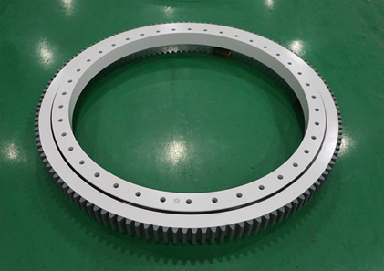
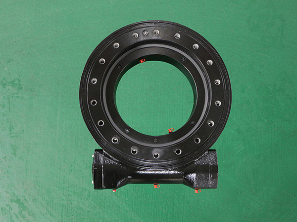
Поворотное приводное устройство также называется поворотным редуктором, зубчатым редуктором, поворотным редуктором, поворотным механизмом и парой поворотных приводов. Все они представляют собой редукторы, которые используют поворотные подшипники в качестве основной опоры, а вспомогательный источник привода использует шестерни или червяки в качестве приводных частей для достижения функций замедления и полного вращения. В состав поворотного привода в основном входят шестерни (или червяки), поворотные подшипники, двигатели, корпуса и основания. Поворотный привод можно в основном разделить на поворотный привод с одним червячным приводом, поворотный привод с двойным червячным приводом и специальный тип поворотного привода.

Классификация приводов поворота

WE Series Slewing Drive

1. Классификация по форме передачи

В соответствии с формой переменной передачи поворотного привода, его можно разделить на поворотный привод с зубчатой ​​передачей и поворотный привод с червячной передачей, унаследовав характеристики зубчатой ​​передачи и червячной передачи. Эти два поворотных привода могут быть адаптированы для средне-высоких и низких скоростей соответственно. Что касается грузоподъемности, характеристики червячной передачи лучше, чем у зубчатой ​​передачи, и когда используется червячная передача с огибающей, ее грузоподъемность, антидеформационная способность и жесткость трансмиссии дополнительно улучшаются, но червячная передача Тип поворотного привода более эффективен с точки зрения КПД. В отличие от поворотного привода зубчатого типа, поворотный привод зубчатого типа делится на поворотный привод с прямым зубом, поворотный привод с косозубыми зубьями и поворотный привод со спиральным корпусом.

2. Классификация по открытости привода поворота.

По степени открытости передаточного механизма поворотного привода поворотный привод можно разделить на открытый и закрытый. Как правило, открытая структура в основном используется в приложениях, где окружающая среда слишком суровая, а цикл обслуживания и обслуживания короткий. Открытая конструкция удобнее для деталей. Осмотр, техническое обслуживание и ремонт продукта также более удобны для замены. Однако замкнутая конструкция может обеспечить более длительный жизненный цикл обслуживания в тех случаях, когда условия окружающей среды не сильно изменились, а уровень загрязнения окружающей среды ниже среднего уровня.

3. Классификация по тяговому усилию.

В зависимости от типа работы конструкции поворотного привода его можно разделить на легкий поворотный привод, средний поворотный привод и тяжелый поворотный привод. В зависимости от мощности, размера, собственного веса поворотного привода и его применения в различных областях и на различных машинах для достижения своих собственных функций поворотный привод для легких режимов работы имеет малый вес, а его возможности по нагрузке и замедлению подходят для работы на высоких скоростях (≥ 10 об / мин), вибрация, ударные нагрузки и т.д. -скоростной (≤3 об / мин), тяжелые и непостоянные рабочие условия.

4. Классификация по структуре приводного состава.

По составу приводного устройства он делится на привод вертикальный и привод горизонтального поворота. Вертикальный поворотный привод означает, что тяговый двигатель и ходовое колесо расположены вертикально, а тяговый двигатель находится вертикально над ходовым колесом. Преимущества: малый радиус вращения, высокий уровень защиты, удобство обслуживания и т. Д., Но высокая стоимость изготовления; Горизонтальный привод означает, что тяговый двигатель и ходовое колесо параллельны, а тяговый двигатель в основном соосен с подвижным колесом и расположен горизонтально. Он имеет преимущества компактной конструкции, простоты и небольшой монтажной высоты.

Применение поворотного привода

SE Series Slewing Drive

Поняв, что такое поворотный привод, давайте рассмотрим его конкретное применение. Редуктор поворота можно использовать в случаях, когда требуется полное вращение и регулируемая скорость. Когда необходимо добиться большей передачи крутящего момента, более точной передачи движения или выбора механизма с компактной структурой корпуса и более высокими требованиями к интеграции, поворотный привод является хорошим решением.

1. Сфера лучевых транспортных средств.

В основных компонентах традиционного поворотного узла тележки с балкой в ​​основном используются традиционные изделия с поворотными кольцами. По сравнению с поворотным приводом поворотное кольцо не имеет внешней оболочки, и его коррозионная стойкость не идеальна, и для управления колесами используются гидроцилиндры. Что касается системы, диапазон углов поворота шины также сильно ограничен. Выбор поворотного приводного устройства в качестве поворотного компонента может не только улучшить коррозионную стойкость компонента, но также увеличить угол поворота каждой группы шин.

2. Сфера автовышки.

Автовышки – важная область применения поворотного привода. Как правило, высотные рабочие грузовики требуют, чтобы хозяин имел более высокий коэффициент безопасности. Высокая безопасность поворотного привода (самоблокировка червячных передач) – большинство пользователей выбирают его в качестве аксессуара для подъемных рабочих платформ. С другой стороны, червячная передача имеет большее передаточное отношение, поэтому при одновременном повышении коэффициента безопасности В главном двигателе можно не использовать набор червячных редукторов для главного двигателя, тем самым снижая стоимость изготовления главного двигателя.

3. Сфера производства фотоэлектрической энергии.

Фотогальваническое производство энергии – важная область применения поворотных приводов. Солнечные фотоэлектрические модули с поворотным приводом в качестве вращающейся части могут точно регулировать угол поворота и угол возвышения хоста в соответствии с различным положением солнца в течение дня. Солнечные батареи всегда в хорошем состоянии. Угол приема.

4. Производство энергии ветра

Подобно фотоэлектрической генерации энергии, поворотный привод может быть применен к рыскающей части ветрогенератора, чтобы реализовать горизонтальное вращение механизма на 360 °, чтобы лучше регулировать угол приема.

5. Сфера когтей строительной техники.

Вспомогательное оборудование для строительной техники – это новая область применения поворотного привода. Поворотный привод используется в качестве кулачка вращающегося механизма, что делает конструктивную структуру более лаконичной, что делает ее более удобной в использовании и обслуживании. В то же время червячный привод имеет большее передаточное число, что приводит к появлению когтей и т. Д. Точность позиционирования вспомогательных средств строительной техники также значительно улучшена.

6. Область промышленных роботов.

Благодаря компактной конструкции и короткой приводной цепи поворотный привод легче достичь более высокой точности и легче осуществлять цифровое управление, поэтому он также широко используется в области промышленных роботов. В последнее время роботы, созданные на основе AGV (мобильных роботов), роботов для точечной сварки, сварочных роботов, роботов для дуговой сварки, роботов для лазерной обработки, вакуумных роботов, чистых роботов и других разновидностей, используются в поворотных приводах.

¿Qué es un accionamiento giratorio, cuáles son su clasificación y áreas de aplicación?

El accionamiento de giro es un mecanismo de reducción de giro con una fuente de alimentación de accionamiento integrada. El anillo de giro se utiliza como parte principal de la transmisión y como accesorio del mecanismo. Su esencia es un motor de imán permanente con un gran par. Este producto también se denomina reductor giratorio, accionamiento giratorio. En comparación con los productos giratorios tradicionales, es fácil de instalar, fácil de mantener y ahorra espacio de instalación en mayor medida. Se utiliza principalmente en camiones con vigas, vehículos de trabajo aéreo, robots industriales, generación de energía fotovoltaica, generación de energía eólica y garras de maquinaria de construcción, etc.

¿Qué es un accionamiento giratorio?

El dispositivo de accionamiento de giro también se denomina reductor de giro, reductor de engranajes, reductor de plataforma giratoria, mecanismo de giro y par de accionamiento de giro. Todos son tipos de reductores que utilizan cojinetes giratorios como soporte principal, y la fuente de impulsión auxiliar utiliza engranajes o tornillos sinfín como piezas impulsoras para lograr funciones de desaceleración y rotación de círculo completo. La composición del mecanismo de giro incluye principalmente engranajes (o tornillos sin fin), cojinetes de giro, motores, carcasas y bases. La unidad de giro se puede dividir básicamente en una unidad de giro de un solo tornillo sin fin, una unidad de giro de doble tornillo sin fin y un tipo especial de unidad de giro.

Clasificación de accionamientos giratorios

WE Series Slewing Drive

1. Clasificación según la forma de transmisión

De acuerdo con la forma de transmisión variable de la transmisión giratoria, se puede dividir en transmisión giratoria de engranajes y transmisión giratoria de tornillo sin fin, heredando las características de transmisión por engranajes y engranaje helicoidal. Estos dos accionamientos giratorios se pueden adaptar a aplicaciones de velocidad media-alta y baja respectivamente. En términos de capacidad de carga, el rendimiento del tipo de tornillo sin fin es mejor que el del tipo de diente, y cuando se adopta la transmisión de tornillo sin fin, su capacidad de carga, capacidad anti-deformación y rigidez de transmisión se mejoran aún más, pero el engranaje sinfín El tipo de accionamiento giratorio es más eficiente en términos de eficiencia. Inferior a la transmisión de giro de tipo engranaje, la transmisión de giro de tipo engranaje se divide en una transmisión de giro de tipo de diente recto, una transmisión de giro de tipo de diente helicoidal y una transmisión de giro de tipo voluta.

2. Clasificación según la apertura del mecanismo de giro.

De acuerdo con la apertura del mecanismo de transmisión de la transmisión de giro, la transmisión de giro se puede dividir en abierta y cerrada. Generalmente, la estructura abierta se utiliza principalmente en aplicaciones donde el entorno es demasiado severo y el ciclo de mantenimiento y mantenimiento es corto. La estructura abierta es más conveniente para las piezas. La inspección, el mantenimiento y el mantenimiento del producto también son más convenientes para su reemplazo. Sin embargo, la estructura cerrada puede proporcionar un ciclo de vida de mantenimiento más largo en ocasiones donde las condiciones ambientales no han cambiado mucho y el nivel de contaminación ambiental está por debajo del nivel medio.

3. Clasificación según la potencia motriz

Según el tipo de funcionamiento de la estructura del accionamiento de giro, se puede dividir en accionamiento de giro ligero, accionamiento de giro medio y accionamiento de giro pesado. De acuerdo con la potencia, el tamaño, el peso muerto y la aplicación del accionamiento de giro en diferentes campos y máquinas para lograr sus propias funciones, el accionamiento de giro de servicio liviano es liviano y sus capacidades de carga y desaceleración son adecuadas para alta velocidad (≥ 10 rpm), vibraciones, cargas de impacto, etc. Condiciones de trabajo: el accionamiento de giro de tamaño mediano es adecuado para altas velocidades (≥10 rpm), vibraciones, cargas de impacto y otras condiciones de trabajo, y el accionamiento de giro de servicio pesado es adecuado para altas -velocidad (≤3 rpm), condiciones de trabajo intermitentes y de servicio pesado.

4. Clasificación según la estructura de la composición de la transmisión.

Según la composición del dispositivo de accionamiento, se divide en accionamiento vertical y accionamiento de giro horizontal. La transmisión de giro vertical significa que el motor de tracción y la rueda motriz son verticales, y el motor de tracción está en posición vertical sobre la rueda motriz. Tiene las ventajas de un radio de giro pequeño, un alto nivel de protección, un mantenimiento conveniente, etc., pero un alto costo de fabricación; accionamiento horizontal significa que el motor de tracción y la rueda de desplazamiento son paralelos, y el motor de tracción es principalmente coaxial con la rueda de desplazamiento y es horizontal. Tiene las ventajas de una estructura compacta, simplicidad y baja altura de instalación.

Aplicación de la unidad de giro

SE Series Slewing Drive

Después de comprender qué es la unidad giratoria, echemos un vistazo a su aplicación específica. El reductor giratorio se puede utilizar en ocasiones que requieran rotación de círculo completo y requisitos de velocidad variable. Cuando es necesario lograr una transmisión de potencia de par mayor, una transmisión de movimiento de mayor precisión o la selección de un mecanismo con una estructura de carrocería compacta y un mayor requisito de integración, la unidad de giro es una buena solución.

1. El campo de los vehículos de transporte de vigas

Los componentes centrales del conjunto de giro de camión de viga tradicional utilizan principalmente productos de anillo de giro tradicionales. En comparación con la transmisión giratoria, la corona giratoria no tiene una carcasa exterior y la resistencia a la corrosión no es ideal, y se utilizan cilindros hidráulicos para impulsar la dirección de los neumáticos. En términos del sistema, el rango del ángulo de rotación del neumático también está muy restringido. La selección de un dispositivo de accionamiento giratorio como componente giratorio no solo puede mejorar la resistencia a la corrosión del componente, sino también aumentar el ángulo de dirección de cada grupo de neumáticos.

2. El campo de los vehículos de trabajo aéreo

Los camiones de trabajo aéreo son un área de aplicación importante de la transmisión giratoria. Generalmente, los camiones de trabajo de gran altitud requieren que el anfitrión tenga un factor de seguridad más alto. La alta seguridad del mecanismo de giro (autobloqueo de los engranajes helicoidales) hace que la mayoría de los usuarios lo elijan como accesorio de plataforma de trabajo aérea.Por otro lado, la transmisión de engranajes helicoidales tiene una relación de velocidad de transmisión mayor, de modo que al tiempo que mejora el factor de seguridad del motor principal, también se puede omitir un conjunto de reductores de tornillo sin fin para el motor principal, reduciendo así el costo de fabricación del motor principal.

3. El campo de la generación de energía fotovoltaica

La generación de energía fotovoltaica es un campo de aplicación importante de los accionamientos giratorios. Los módulos solares fotovoltaicos con accionamiento giratorio como parte giratoria pueden ajustar con precisión el ángulo de rotación y elevación del host de acuerdo con las diferentes posiciones del sol durante el día. Los paneles solares están siempre en buenas condiciones. Ángulo de recepción.

4. Generación de energía eólica

Similar a la generación de energía fotovoltaica, la unidad de giro se puede aplicar a la parte de guiñada del generador eólico para realizar la rotación horizontal de 360 ​​° del mecanismo, a fin de ajustar mejor el ángulo de recepción.

5. El campo de las garras de maquinaria de construcción.

Los equipos auxiliares de maquinaria de construcción son un nuevo campo de aplicación de los accionamientos giratorios. La unidad de giro se utiliza como garra del mecanismo giratorio, lo que hace que la estructura de diseño sea más concisa, lo que es más propicio para el uso y el mantenimiento. Al mismo tiempo, el engranaje helicoidal tiene una relación de reducción mayor, lo que hace que las garras, etc. La precisión de posicionamiento de las ayudas para maquinaria de construcción también se haya mejorado considerablemente.

6. El campo de los robots industriales

Debido a la estructura compacta y la cadena de transmisión corta, el accionamiento de giro es más fácil de lograr una mayor precisión y más fácil de llevar a cabo el control digital, por lo que también se usa ampliamente en el campo de los robots industriales. Recientemente, los robots derivados de AGV (robots móviles), robots de soldadura por puntos, robots de soldadura, robots de soldadura por arco, robots de procesamiento láser, robots de vacío, robots limpios y otras variedades tienen aplicaciones de accionamiento giratorio.

What is a slewing drive, what are its classification and application areas?

The slewing drive is a slewing reduction mechanism with an integrated driving power source. The slewing ring is used as the main transmission part and the mechanism attachment. Its essence is a permanent magnet motor with large torque. This product is also called a slewing reducer, a slewing drive, Compared with traditional rotary products, it is easy to install, easy to maintain, and save installation space to a greater extent. It is mainly used in beam trucks, aerial work vehicles, industrial robots, photovoltaic power generation, wind power generation, and construction machinery claws, etc. field.

What is a slewing drive

The slewing drive device is also called a slewing reducer, a gear reducer, a turntable reducer, a slewing mechanism, and a slewing drive pair. They are all types of reducers that use slewing bearings as the main support, and the auxiliary drive source uses gears or worms as the driving parts to achieve deceleration and full-circle rotation functions. The composition of the slewing drive mainly includes gears (or worms), slewing bearings, motors, housings, and bases. Slewing drive can be basically divided into single worm drive slewing drive, double worm drive slewing drive and special type of slewing drive.

Classification of slewing drives

WE Series Slewing Drive

1. Classification according to the transmission form

According to the variable transmission form of slewing drive, it can be divided into gear slewing drive and worm gear slewing drive, inheriting the characteristics of gear drive and worm gearing. These two slewing drives can be adapted to medium-high and low-speed applications respectively. In terms of carrying capacity, the performance of the worm gear type is better than that of the tooth type, and when the envelope worm transmission is adopted, its carrying capacity, anti-deformation ability and transmission rigidity are further improved, but the worm gear type slewing drive is more efficient in terms of efficiency. Inferior to the gear type slewing drive, the gear type slewing drive is divided into a straight tooth type slewing drive, a helical tooth type slewing drive, and a volute type slewing drive.

2. Classification according to the openness of the slewing drive

According to the openness of the slewing drive transmission mechanism, the slewing drive can be divided into open and closed. Generally, the open structure is mostly used in applications where the environment is too harsh and the maintenance and maintenance cycle is short. The open structure is more convenient for parts. The inspection, maintenance and maintenance of the product are also more convenient for replacement. However, the closed structure can provide a longer maintenance life cycle in occasions where the environmental conditions have not changed much and the environmental pollution level is below the medium level.

3. Classification according to driving power

According to the structure operation type of the slewing drive, it can be divided into light slewing drive, medium slewing drive and heavy slewing drive. According to the slewing drive’s power, size, dead weight, and application in different fields and machines to achieve its own functions, the light-duty slewing drive is light in weight, and its load and deceleration capabilities are suitable for high-speed (≥10rpm), vibration, impact loads, etc. Working conditions: The medium-sized slewing drive is suitable for high-speed (≥10rpm), vibration, impact load and other working conditions, and the heavy-duty slewing drive is suitable for high-speed (≤3rpm), heavy-duty, and intermittent working conditions.

4. Classification according to the structure of the drive composition

According to the composition of the drive device, it is divided into vertical drive and horizontal slewing drive. Vertical slewing drive means that the traction motor and the traveling wheel are vertical, and the traction motor is upright above the traveling wheel. It has the advantages of small gyration radius, high protection level, convenient maintenance, etc., but high manufacturing cost; horizontal drive means that the traction motor and the traveling wheel are parallel, and the traction motor is mostly coaxial with the traveling wheel and is horizontal. It has the advantages of compact structure, simplicity, and low installation height.

Application of slewing drive

SE Series Slewing Drive

After understanding what the slewing drive is, let’s take a look at its specific application. The slewing reducer can be used in the occasions that require full-circle rotation and variable speed requirements. When it is necessary to achieve larger torque power transmission, higher precision motion transmission, or the selection of a mechanism with a compact body structure and a higher requirement for integration, the slewing drive Is a good solution.

1. The field of beam transport vehicles

The core components of the traditional beam truck slewing assembly mostly use traditional slewing ring products. Compared with the slewing drive, the slewing ring does not have an outer shell, and the corrosion resistance is not ideal, and hydraulic cylinders are used to drive the steering of the tires. In terms of the system, the rotation angle range of the tire is also greatly restricted. The selection of a slewing drive device as a slewing component can not only improve the corrosion resistance of the component, but also increase the steering angle of each group of tires.

2. The field of aerial work vehicles

Aerial work trucks are an important application area of ​​slewing drive. Generally, high-altitude work trucks require the host to have a higher safety factor. The high safety of slewing drive (self-locking of worm gears) is the majority of users choose it as an aerial work platform accessory On the other hand, the worm gear transmission has a larger transmission speed ratio, so that while improving the safety factor of the main engine, a set of worm gear reducers can also be omitted for the main engine, thereby reducing the manufacturing cost of the main engine.

3. The field of photovoltaic power generation

Photovoltaic power generation is an important application field of slewing drive. Solar photovoltaic modules with slewing drive as a rotating part can accurately adjust the rotation and elevation angle of the host according to the different positions of the sun during the day. The solar panels are always in good condition. Receiving angle.

4. Wind power generation

Similar to photovoltaic power generation, the slewing drive can be applied to the yaw part of the wind generator to realize the horizontal 360° rotation of the mechanism, so as to better adjust the receiving angle.

5. The field of construction machinery claws

Construction machinery auxiliary equipment is a new application field of slewing drive. The slewing drive is used as the claw of the rotating mechanism, which makes the design structure more concise, which is more conducive to use and maintenance. At the same time, the worm gear drive has a larger reduction ratio, which makes the claws, etc. The positioning accuracy of construction machinery aids has also been greatly improved.

6. The field of industrial robots

Due to the compact structure and short transmission chain, the slewing drive is easier to achieve higher accuracy and easier to carry out digital control, so it is also widely used in the field of industrial robots. Recently, robots derived from AGV (mobile robots), spot welding robots, welding robots, arc welding robots, laser processing robots, vacuum robots, clean robots and other varieties have slewing drive applications.

Методы обслуживания и меры предосторожности при обслуживании поворотных подшипников

Существует много типов подшипников, и поля и оборудование, используемое для каждого типа подшипников, будут разными. Среди них поворотный подшипник может вращаться и использоваться во многих машинах и оборудовании. Можно сказать, что это сфера использования. Существует очень широкий ассортимент подшипников, так каковы методы обслуживания опорно-поворотного устройства и каковы меры предосторожности в процессе обслуживания? Производитель поворотного кольца представил нам следующее подробное описание.

Метод обслуживания поворотного подшипника

1. После 100 часов работы поворотного устройства необходимо проверить усилие предварительной затяжки болтов, а затем каждые 500 часов работы необходимо поддерживать достаточное усилие предварительной затяжки.

2. Если во время использования поворотное кольцо внезапно усиливается, его следует немедленно отключить для проверки, поиска и устранения неисправностей, а также разборки и осмотра, если это необходимо.

3. Дорожки качения поворотного подшипника регулярно заполняются консистентной смазкой. Как правило, заправка шариковых подшипников осуществляется каждые 100 часов работы, а заправка роликовых подшипников – каждые 50 часов.

4. Поверхность зубьев поворотного подшипника следует часто очищать от мусора и смазывать соответствующей смазкой.

5. Опорно-поворотный подшипник и поверхность зубьев поворотного кольца следует очистить за 10 смен и нанести смазку повторно.

Вопросы, требующие внимания при обслуживании поворотного подшипника

news2

1. Монтажная опора поворотного устройства должна иметь достаточную жесткость, а монтажная поверхность должна быть плоской. Перед сборкой опорно-поворотного устройства необходимо снять напряжение с опоры. Поворотный подшипник и поворотное кольцо следует ремонтировать и обслуживать, чтобы уменьшить деформацию опоры поворотного кольца. Опора должна быть собрана во время сборки. Поверхность контакта с поворотным подшипником необходимо очистить.

2. При использовании поворотных подшипников и поворотных подшипников следует обращать внимание на изменение шума и крутящего момента сопротивления повороту. Если есть какие-либо отклонения в обслуживании опорно-поворотных устройств и опорно-поворотных устройств, их следует разобрать для проверки. Опорно-поворотные устройства следует поднимать или хранить горизонтально, а не вертикально. Поднимите или храните, чтобы избежать деформации.

3. Перед затяжкой болтов необходимо проверить опорный подшипник и опорную опору на предмет зацепления с зубчатыми колесами. Состояние зацепления должно соответствовать требованиям точности зубчатой ​​передачи, то есть пятен контакта, распределенных на поверхности зуба после того, как зубчатая пара работает при небольшом торможении. Направление высоты зуба составляет не менее 25%, а направление длины зуба – не менее 30%.

4. Опорно-поворотный подшипник и поворотное кольцо. Чтобы обеспечить надежность работы болта и избежать отсутствия усилия предварительной затяжки болта, опорно-поворотный подшипник и поворотное кольцо должны быть проверены на момент предварительной затяжки болтов через 100 и 500 часов. часы работы поворотного круга. Момент предварительной затяжки следует проверять каждые 1000 часов работы.

Срок службы опорно-поворотного устройства во время работы прямо пропорционален проводимому на нем техническому обслуживанию. Хороший уход за поворотным кольцом также позволяет избежать его выхода из строя. Указанные выше методы обслуживания опорно-поворотного устройства являются лишь его частью. Друзья, которые хотят знать, могут посетить сайт нашей компании. Опорно-поворотное устройство производства LDB Bearing Co., Ltd. хорошего качества, что позволяет эффективно повысить производительность труда и стабильность оборудования. Вы можете позвонить на нашу горячую линию или оставить сообщение внизу сайта.

Métodos de mantenimiento de los cojinetes de giro y precauciones de mantenimiento

Hay muchos tipos de cojinetes y los campos y equipos utilizados por cada tipo de cojinete serán diferentes. Entre ellos, el rodamiento giratorio se puede girar y utilizar en muchos equipos y máquinas. Se puede decir que es el ámbito de uso. Existe una gama muy amplia de rodamientos, entonces, ¿cuáles son los métodos de mantenimiento del anillo giratorio y cuáles son las precauciones en el proceso de mantenimiento? El fabricante del anillo giratorio nos dio la siguiente introducción detallada.

Método de mantenimiento del cojinete giratorio.

1. Después de 100 horas de funcionamiento del anillo giratorio, se debe comprobar la fuerza de apriete previo de los pernos y, a partir de entonces, cada 500 horas de funcionamiento, se debe mantener una fuerza de apriete previa suficiente.

2. Cuando el anillo giratorio está en uso, si el ruido, el impacto o la potencia aumentan repentinamente, debe apagarse inmediatamente para su inspección, solución de problemas y desmontaje e inspección si es necesario.

3. Las pistas de rodadura del rodamiento giratorio se llenan regularmente de grasa. Generalmente, los rodamientos de bolas se repostan cada 100 horas de funcionamiento y los rodamientos de rodillos se repostan cada 50 horas.

4. La superficie del diente del cojinete giratorio debe limpiarse de escombros con frecuencia y cubrirse con la grasa correspondiente.

5. El cojinete giratorio y la superficie del diente del anillo giratorio deben limpiarse durante 10 turnos y debe volver a aplicar grasa.

Asuntos que requieren atención en el mantenimiento de los cojinetes de giro

news2

1. El soporte de montaje del anillo giratorio debe tener suficiente rigidez y la superficie de montaje debe ser plana. El soporte debe someterse a un alivio de tensión antes de montar el anillo giratorio. El rodamiento giratorio y el anillo giratorio deben repararse y mantenerse para reducir la deformación del soporte del anillo giratorio. El soporte debe montarse durante el montaje. Se debe limpiar la superficie de contacto con el rodamiento giratorio.

2. Al utilizar cojinetes giratorios y cojinetes giratorios, se debe prestar atención a los cambios en el ruido y el par de resistencia al giro. Si hay alguna anomalía en el mantenimiento de los cojinetes giratorios y los cojinetes giratorios, deben desmontarse para su inspección. Los cojinetes giratorios deben izarse o almacenarse horizontalmente, no verticalmente. Levante o almacene para evitar deformaciones.

3. Antes de apretar los pernos, se debe verificar el engranaje del cojinete de giro y el soporte de giro. La condición de engrane debe cumplir con los requisitos de precisión del engranaje, es decir, los puntos de contacto distribuidos en la superficie del diente después de que el par de engranajes funciona con un ligero frenado. La dirección de la altura del diente no es inferior al 25% y la dirección de la longitud del diente no es inferior al 30%.

4. Cojinete de giro y anillo de giro Para garantizar la fiabilidad del trabajo de los pernos y evitar la falta de fuerza de apriete previo del perno, se debe verificar el par de apriete de los pernos en el cojinete de giro y el anillo de giro después de 100 horas y 500 horas. Horas de funcionamiento del anillo giratorio. El par de apriete previo debe comprobarse cada 1000 horas de trabajo.

La vida útil del anillo giratorio durante el trabajo es directamente proporcional al mantenimiento que se le realiza. Un buen mantenimiento del anillo giratorio también es una forma de evitar la falla del anillo giratorio. Los métodos de mantenimiento del anillo giratorio de arriba son solo una parte. Los amigos que quieran saber pueden consultar el sitio web de nuestra empresa. El anillo de giro producido por LDB Bearing Co., Ltd. es de buena calidad, lo que puede mejorar efectivamente la productividad laboral y la estabilidad del equipo. Le invitamos a llamar a nuestra línea directa o dejar un mensaje en la parte inferior del sitio web.

Slewing bearing maintenance methods and maintenance precautions

There are many types of bearings, and the fields and equipment used by each type of bearing will be different. Among them, the slewing bearing can be rotated and used in many equipment and machines. It can be said to be the scope of use. There is a very wide range of bearings, so what are the maintenance methods of the slewing ring and what are the precautions in the maintenance process? The slewing ring manufacturer gave us the following detailed introduction.

Maintenance method of slewing bearing

1. After 100 hours of operation of the slewing ring, the pre-tightening force of the bolts should be checked, and every 500 hours of operation thereafter, sufficient pre-tightening force must be maintained.

2. When the slewing ring is in use, if noise, impact, or power suddenly increases, it should be shut down immediately for inspection, troubleshooting, and disassembly and inspection if necessary.

3. The raceways of the slewing bearing are regularly filled with grease. Generally, the ball bearings are refueled every 100 hours of operation, and the roller bearings are refueled every 50 hours.

4. The tooth surface of the slewing bearing should be cleaned of debris frequently and coated with corresponding grease.

5. The slewing bearing and slewing ring tooth surface should be cleaned up for 10 shifts, and grease should be reapplied.

Matters needing attention in maintenance of slewing bearing

news2

1. The mounting support of the slewing ring must have sufficient rigidity and the mounting surface should be flat. The support should be subjected to stress relief before assembling the slewing ring. The slewing bearing and slewing ring should be repaired and maintained to reduce the deformation of the slewing ring support. The support should be assembled during assembly. The contact surface with the slewing bearing must be cleaned.

2. When using slewing bearings and slewing bearings, attention should be paid to changes in noise and slewing resistance torque. If there is any abnormality in the maintenance of slewing bearings and slewing bearings, they should be disassembled for inspection. The slewing bearings must be hoisted or stored horizontally, not vertically. Lift or store to avoid deformation.

3. Before the bolts are tightened, the slewing bearing and slewing support should be checked for gear meshing. The meshing condition should meet the requirements of gear accuracy, that is, the contact spots distributed on the tooth surface after the gear pair runs under slight braking. The tooth height direction is not less than 25%, and the tooth length direction is not less than 30%.

4. Slewing bearing and slewing ring In order to ensure the reliability of bolt work and avoid the lack of bolt pre-tightening force, the slewing bearing and slewing ring should be checked for the pre-tightening torque of the bolts after 100 hours and 500 hours of operation of the slewing ring. The pre-tightening torque should be checked every 1000 hours of work.

The service life of the slewing ring during work is directly proportional to the maintenance performed on it. Good maintenance of the slewing ring is also a way to avoid the failure of the slewing ring. The maintenance methods of the slewing ring above are only part of it. Friends who want to know can check our company website. The slewing ring produced by LDB Bearing Co., Ltd. is of good quality, which can effectively improve labor productivity and equipment stability. You are welcome to call our hotline or leave a message at the bottom of the website.

Причины и способы устранения частых неисправностей поворотных приводов

В существующем механизме трансмиссии диапазон применения поворотного привода очень широк, включая применение таких продуктов, как высотные подъемные платформы, пожарные машины, морские краны и машины для перекачки бревен. В сложной прикладной среде поворотное приводное устройство неизбежно выйдет из строя по разным причинам. Приведенный ниже редактор разобрал некоторые распространенные неисправности и способы их устранения, и надеется быть полезным для всех.

Распространенные причины выхода из строя поворотно-приводных устройств

Spur Gear Drive

1. Вал приводной колонны винта.

(1) Тандем вала, вызванный сломанными зубьями, из-за чего первичный вал теряет свою осевую сдерживающую силу;

(2) Ведомая шестерня поворотного привода не плотно прикреплена к валу, что приводит к недостаточному натяжению подшипников, что приводит к появлению ряда валов, и это влияет на проблему рулевого управления поворотного привода;

(3) Отклонение зуборезной обработки;

(4) Погрешность угла наклона спирали зубчатого колеса;

(5) Погрешность толщины зуба, неравномерный износ поверхности зуба и преждевременный износ, деформация спинки зуба.

Температура масла поворотного привода слишком высока.

(1) Смазочное масло, используемое в приводе вращения, неквалифицировано или использовалось слишком долго;

(2) В приводе вращения используется слишком много смазочного масла;

(3) Повреждение компонентов поворотного привода, в том числе сильная точечная коррозия шестерен, сломанные зубья, повреждение сепаратора подшипника, внутреннего и внешнего колец, шариков, а также заедание подшипника или серьезная деформация вала;

(4) Снаружи роторный привод покрыт мусором или пылью. Когда вещи складываются в кучу или поверхность корпуса машины долгое время не очищалась, крышка от мусора или пыли может вызвать неполный отвод тепла редуктора и повысить температуру масла;

(5) Охлаждающее устройство вышло из строя или заблокировано. Если охлаждающее устройство заблокировано или охлаждающее устройство сломано из-за длительной работы без очистки внутреннего трубопровода, это приведет к повышению температуры масла поворотного привода;

(6) Перегрузка поворотного привода.

Утечка масла из поворотного привода

Утечка масла поворотного привода: уплотнительное кольцо ведущего вала, уплотнительное кольцо ведомого вала, коробка поворотного привода, крышка смотрового отверстия, отверстие для слива масла внизу и утечка масла сапуна. Возможные причины: крепежные болты не затянуты; на поверхности соединительной коробки железные опилки и закрытие неплотно; корпус поворотного привода деформирован, не плотно прилегает и течет масло; или в вентиляторе слишком много масла.

Привод поворота перегрет или шумит в подшипниковой части.

(1) Недостаточно смазочного масла. Когда уровень смазочного масла недостаточен или редуктор не может достичь разумной высоты из-за утечки масла, это может вызвать высокую температуру или шум в опорной части редуктора;

(2) Притирается крышка подшипника или уплотнение. Когда крышка подшипника или уплотнительная деталь и соединительная деталь изнашиваются из-за неправильной установки, неправильной крышки подшипника или длительного использования, температура подшипника редуктора может быть высокой или может возникать шум;

(3) Подшипник поврежден или изношен. Этот пункт в основном включает в себя повреждение сепаратора подшипника, износ или деформацию внутреннего и внешнего колец, износ или падение шариков, по этим причинам редуктор не сможет нормально работать;

(4) Зазор подшипника слишком велик или слишком мал. Вышеуказанные симптомы могут быть вызваны увеличением зазора между шариком подшипника редуктора и внутренним и наружным кольцами, зазором между внутренним кольцом подшипника и валом, а также зазором между подшипником и торцевой крышкой из-за длительного использовать;

(5) Ключевой рычаг косозубой шестерни ослаблен. Ослабление рукоятки призматической шпонки косозубой шестерни вызовет неплотную посадку между шестерней и валом, что приведет к перегреву или шуму в подшипнике;

Большая вибрация корпуса поворотного привода

Возможные причины вибрации корпуса поворотного привода: ослабление анкерного винта; стяжка повреждена; болт мотора ослаблен; подшипник сильно изношен; шестерня повреждена; вал деформирован и разбалансирован. Эти условия могут быть вызваны ослабленными винтами или неисправностями муфты, износом подшипников и другими причинами, вызванными длительной эксплуатацией.

Подшипник поворотно-приводного устройства сломан.

Трещины подшипников поворотного привода возникают в основном в подшипниках ведущего вала. Основная причина заключается в том, что при движении ведущего вала между внутренним кольцом подшипника и роликами происходит осевое скольжение, в результате чего внутреннее кольцо подшипника перемещается в осевом направлении, в результате чего ролики внутреннего подшипника перемещаются первыми. Повреждение подшипника.

Повреждение приводной шестерни поворота.

Поворотные приводы имеют разные причины поломки зубьев, выкрашивания шестерен, выкрашивания и износа. Ее условно можно разделить на недостаточную контактную усталостную прочность шестерни; дефекты материала шестерен, низкая точность, недостаточная смазка, примеси в смазочном масле и ошибки в межосевом расстоянии шестерен.

Устройство поворотного привода издает ненормальный шум

Возможные причины Редуктор перегружен; нагрузка на рабочую машину неуравновешенная; смазочное масло испортилось; поверхность зуба шестерни изношена или качество изготовления плохое; зазор подшипника слишком велик или слишком мал; есть заживление на поверхности зуба; в ящике есть мусор.

Разобравшись в причинах типичных отказов поворотного приводного устройства, редактор кратко представляет методы ремонта отказа поворотного приводного устройства. Вы можете проверить неисправность в зависимости от конкретной ситуации. Если вы не можете решить эту проблему самостоятельно, вам все равно необходимо обратиться к производителю для ремонта.

Решения типичных неисправностей поворотных приводов

1. Вал приводной колонны винта.

Это может улучшить прочность и точность изготовления шестерни, а также снизить значение шероховатости шестерни и вала. Повышение точности установки и герметичности ведомой шестерни и вала в основном связано с достижением разумной посадки с натягом.

2. Температура масла привода ротора слишком высока.

(1) Персонал может выполнить детальную проверку фактической нагрузки поворотного привода и отрегулировать ее до указанного значения, или его можно заменить на более мощный поворотный привод.

(2) Используйте смазочное масло для удаления излишков масла в строгом соответствии с предписанным количеством масла; или замените смазочное масло.

(3) Удалите мусор и пыль вокруг роторного привода, замените охлаждающее устройство, чтобы удалить засорение.

3. Утечка масла из поворотного привода.

(1) Сальник уплотнительного кольца имеет открытую или легко разбираемую конструкцию.

(2) Установите прокладки и крепежные болты на крышку смотрового отверстия.

(3) Отверстие для возврата масла на подшипнике первичного вала должно быть увеличено соответствующим образом.

(4) Замените деформированный корпус привода.

(5) Правильно установите и откорректируйте уровень масла в вентиляторе.

(6) Кольцевая масляная канавка отлита или механически обработана на поверхности муфты основания вращающегося привода, и имеется несколько отверстий для возврата масла, сообщающихся с кольцевой масляной канавкой. Когда редуктор работает, как только масло проникает в поверхность соединительной коробки, оно входит в кольцевую масляную канавку, а затем течет в масляный бак через отверстие для возврата масла, и смазочное масло не будет вытекать по поверхности коробки в вне корпуса редуктора.

(7) Нанесите слой герметика (например, герметик из силиконовой резины D05) на поверхность коробки, чтобы эффективно предотвратить утечку масла на поверхность коробки.

(8) Улучшите вентиляционную крышку и крышку смотрового отверстия. Внутреннее давление редуктора больше внешнего атмосферного давления – одна из основных причин утечки масла. Если вы попытаетесь сбалансировать давление внутри и снаружи машины, утечку масла можно будет предотвратить. Хотя редуктор имеет вентиляционную крышку, вентиляционное отверстие слишком маленькое, и оно легко может быть заблокировано пылью и маслом. Кроме того, крышку смотрового отверстия необходимо открывать каждый раз при заправке масла. После открытия вероятность утечки масла увеличится один раз, так что исходное место не протечет. Утечки тоже произошли. Вентиляционное отверстие можно увеличить для выравнивания давления внутри и снаружи.

4. Привод поворота перегрет или шумит в подшипниковой части.

(1) Проверьте уровень масла в приводе вращения и долейте смазочное масло;

(2) Затяните болты подшипника и соединительной детали и проверьте установку уплотнения;

(3) Проверьте подшипник и немедленно замените его, если он поврежден;

(4) Если зазор не подходит, отрегулируйте зазор подшипника и замените подшипник, если он не может быть отрегулирован;

(5) Если шпоночная рукоятка косозубой шестерни ослабла, вовремя отправьте ее в ремонт;

5. Вибрация вращающегося корпуса привода велика.

Неисправность может быть устранена затяжкой болтов на лапах и ослабленных винтов мотора; ремонт стяжки; замена подшипника; замена шестерни.

6. Сломан подшипник поворотного привода.

Увеличьте натяг между внутренним кольцом и валом или добавьте стопорное кольцо на внешней стороне внутреннего кольца подшипника, чтобы предотвратить осевое перемещение.

7. Повреждение шестерни поворотного привода.

Повреждение шестерен можно усилить, или можно использовать вязкость обычного смазочного материала для уменьшения потерь смазочного материала и предотвращения ржавчины. Очистите шестерню, чтобы на ее поверхности не осталось загрязнений, замените шестерню, которая не подлежит ремонту, и уделите внимание ежедневному обслуживанию.

8. Поворотный привод издает необычный шум.

При возникновении ненормального шума вы можете заменить новую смазку, чтобы отрегулировать зазор подшипника, проверить подшипник и выполнить работы по очистке или вовремя заменить новые детали.

Выше представлены сортировка и краткое изложение наиболее распространенных причин неисправностей и способов их устранения. Надеюсь, это будет полезно всем.

Causas y soluciones de fallas comunes de los dispositivos de accionamiento giratorio

En el mecanismo de transmisión actual, el rango de aplicación de la unidad de giro es muy amplio, incluida la aplicación de productos como plataformas elevadoras de gran altitud, camiones de bomberos, grúas marinas y máquinas de transferencia de troncos. En un entorno de aplicación complejo, el dispositivo de accionamiento giratorio fallará inevitablemente debido a varias razones. El siguiente editor ha resuelto algunas fallas y soluciones comunes del dispositivo de accionamiento giratorio y espera ser útil para todos.

Causas comunes de fallas de los dispositivos de accionamiento giratorio

Spur Gear Drive

1. Eje de cadena de transmisión giratoria

(1) Eje en tándem causado por dientes rotos que hacen que el eje de entrada pierda su fuerza de restricción axial;

(2) El engranaje impulsado de la transmisión de giro no está bien sujeto al eje, lo que resulta en una interferencia insuficiente en los cojinetes, lo que resulta en una serie de ejes, y el problema de dirección de la transmisión de giro se ve afectado;

(3) Deflexión de mecanizado de engranajes;

(4) Error del ángulo de la hélice del engranaje;

(5) Error de grosor del diente, desgaste desigual de la superficie del diente y desgaste prematuro, deformación de la parte posterior del diente.

La temperatura del aceite del accionamiento giratorio es demasiado alta

(1) El aceite lubricante utilizado por el accionamiento giratorio no está calificado o se ha utilizado durante demasiado tiempo;

(2) Se utiliza demasiado aceite lubricante en el mando giratorio;

(3) Daño a los componentes de la transmisión de giro, incluyendo picaduras severas de engranajes, dientes rotos, daño a la jaula del rodamiento, anillos internos y externos, bolas, así como agarrotamiento del rodamiento o deformación severa del eje;

(4) El exterior del mando giratorio está cubierto de suciedad o polvo. Cuando se amontonan cosas o la superficie del cuerpo de la máquina no se ha limpiado durante mucho tiempo, la cubierta de escombros o polvo puede causar una disipación de calor incompleta del reductor y aumentar la temperatura del aceite;

(5) El dispositivo de enfriamiento falla o está bloqueado. Si el dispositivo de enfriamiento está bloqueado o el dispositivo de enfriamiento está roto debido a un trabajo prolongado sin limpiar la tubería interna, hará que la temperatura del aceite del accionamiento giratorio aumente;

(6) Operación de sobrecarga del accionamiento giratorio.

Fuga de aceite del accionamiento giratorio

La fuga de aceite de la unidad de giro: el anillo de sello del eje impulsor, el anillo de sello del eje impulsado, la caja de transmisión de giro, la tapa del orificio de visualización, el orificio de drenaje de aceite en la parte inferior y la fuga de aceite del respiradero. Las posibles razones incluyen que los pernos de fijación no estén apretados; hay limaduras de hierro en la superficie de la caja de juntas y el cierre no es hermético; la carcasa del accionamiento giratorio está deformada y no encaja bien y tiene fugas de aceite; o el ventilador tiene demasiado aceite.

El accionamiento de giro está sobrecalentado o hay ruido en la parte del cojinete.

(1) Aceite lubricante insuficiente. Cuando el nivel de aceite de lubricación es insuficiente o el reductor no puede alcanzar una altura razonable debido a una fuga de aceite, puede causar alta temperatura o ruido en la parte del cojinete del reductor;

(2) Se frota la tapa del cojinete o la pieza del sello. Cuando la cubierta del cojinete o la pieza de sellado y la pieza de conexión están desgastadas debido a una instalación incorrecta, una cubierta de cojinete incorrecta o un uso prolongado, la temperatura del cojinete del reductor puede ser alta o puede haber ruido;

(3) El cojinete está dañado o desgastado. Este ítem incluye principalmente daños en la jaula del rodamiento, desgaste o deformación de los anillos internos y externos, desgaste o caída de las bolas, estas razones harán que el reductor no pueda funcionar normalmente;

(4) La holgura del rodamiento es demasiado grande o demasiado pequeña. Los síntomas anteriores pueden ser causados ​​cuando el espacio entre la bola del rodamiento reductor y los aros interior y exterior, el espacio entre el aro interior del rodamiento y el eje, y el espacio entre el rodamiento y la tapa del extremo aumentan debido al largo plazo. utilizar;

(5) La manija de la llave del engranaje helicoidal está suelta. La holgura de la manija de la llave del engranaje helicoidal causará la falta de ajuste apretado entre el engranaje y el eje, lo que resultará en un sobrecalentamiento o ruido en el cojinete;

Gran vibración del cuerpo de accionamiento giratorio

Las posibles razones de la vibración del cuerpo de accionamiento giratorio incluyen: el tornillo de anclaje está suelto; el acoplador está dañado; el tornillo del motor está suelto; el cojinete está muy desgastado; el engranaje está dañado; el eje está deformado y desequilibrado. Estas condiciones pueden deberse a tornillos sueltos o fallas del acoplador, desgaste de los cojinetes y otras razones causadas por el funcionamiento a largo plazo.

El cojinete del dispositivo de accionamiento giratorio está roto.

Las grietas del cojinete de impulsión de giro se producen principalmente en el cojinete del eje impulsor. La razón principal es que cuando el eje impulsor se mueve, se producirá un deslizamiento axial entre el aro interior del rodamiento y los rodillos, lo que provocará que el aro interior del rodamiento se mueva axialmente, lo que hará que los rodillos interiores del rodamiento se muevan primero. Daño al rodamiento.

Daños en el engranaje impulsor giratorio

Los accionamientos rotativos tienen diferentes motivos para la rotura de dientes, picaduras de engranajes, desconchado y desgaste. Se puede dividir aproximadamente en resistencia a la fatiga por contacto insuficiente del engranaje; defectos en el material de los engranajes, mala precisión, lubricación inadecuada, impurezas en el aceite lubricante y errores en la distancia entre ejes de los engranajes.

El dispositivo de accionamiento giratorio tiene un ruido anormal

Causas posibles El reductor está sobrecargado; la carga de la máquina de trabajo está desequilibrada; el aceite lubricante está deteriorado; la superficie del diente del engranaje está desgastada o la calidad de fabricación es deficiente; la holgura del rodamiento es demasiado grande o demasiado pequeña; hay adherencia en la superficie del diente; hay escombros en la caja.

Después de comprender las causas de las fallas comunes del dispositivo de la unidad de giro, el editor presenta brevemente los métodos de reparación de la falla del dispositivo de la unidad de giro. Puede verificar la falla de acuerdo con la situación específica. Si no puede resolverlo por sí mismo, aún debe comunicarse con el fabricante para su reparación.

Soluciones a fallas comunes de dispositivos de accionamiento giratorio

1. Eje de cadena de transmisión giratoria

Puede mejorar la resistencia y precisión de fabricación del engranaje y reducir el valor de rugosidad del engranaje y el eje. La mejora de la precisión y la estanqueidad de la instalación del engranaje impulsado y el eje es principalmente para lograr un ajuste de interferencia razonable.

2. La temperatura del aceite del mando giratorio es demasiado alta.

(1) El personal puede realizar una inspección detallada de la carga real de la unidad de giro y ajustarla al valor especificado, o se puede reemplazar con una unidad de giro de mayor potencia.

(2) Utilice aceite lubricante para eliminar el exceso de aceite estrictamente de acuerdo con la cantidad prescrita de aceite; o reemplace el aceite lubricante.

(3) Quite la suciedad y el polvo alrededor de la unidad giratoria, reemplace el dispositivo de enfriamiento para eliminar el bloqueo.

3. Fuga de aceite del accionamiento giratorio

(1) El prensaestopas del anillo de sellado adopta una estructura abierta o una estructura fácilmente desmontable.

(2) Instale juntas y pernos de fijación en la tapa de la mirilla.

(3) El orificio de retorno de aceite en el cojinete del eje de entrada debe agrandarse adecuadamente.

(4) Reemplace la carcasa de transmisión deformada.

(5) Instale y corrija correctamente el nivel de aceite del ventilador.

(6) Se moldea o mecaniza una ranura de aceite anular en la superficie de la caja de la base del impulsor giratorio, y hay múltiples orificios de retorno de aceite que se comunican con la ranura de aceite anular. Cuando el reductor está funcionando, una vez que el aceite penetra en la superficie de la caja de unión, entrará en la ranura de aceite anular y luego fluirá hacia el tanque de aceite a través del orificio de retorno de aceite, y el aceite lubricante no se escapará a lo largo de la superficie de la caja hacia el fuera de la carcasa del reductor.

(7) Aplique una capa de sellador (como sellador de caucho de silicona D05) en la superficie de la caja para prevenir eficazmente las fugas de aceite en la superficie de la caja.

(8) Mejore la tapa de ventilación y la tapa del orificio de inspección. La presión interna del reductor es mayor que la presión atmosférica externa es una de las principales razones de las fugas de aceite. Si intenta equilibrar la presión dentro y fuera de la máquina, se pueden evitar las fugas de aceite. Aunque el reductor tiene una tapa de ventilación, el orificio de ventilación es demasiado pequeño y es fácil que se bloquee con polvo y aceite. Además, la tapa del orificio de inspección debe abrirse cada vez que se reposta aceite. Una vez abierto, la posibilidad de fuga de aceite aumentará una vez, para que el lugar original no gotee. También se produjeron fugas. El orificio de ventilación se puede ampliar para igualar la presión interior y exterior.

4. La transmisión de giro está sobrecalentada o hay ruido en la parte del cojinete.

(1) Verifique el nivel de aceite del mando rotatorio y agregue aceite lubricante;

(2) Apriete los pernos del cojinete y la pieza de conexión, y verifique la instalación del sello;

(3) Verifique el cojinete y reemplácelo inmediatamente si está dañado;

(4) Si la holgura no es adecuada, ajuste la holgura del rodamiento y reemplace el rodamiento si no se puede ajustar;

(5) Si el mango de la llave del engranaje helicoidal está suelto, envíelo a tiempo para su reparación;

5. La vibración del cuerpo impulsor giratorio es grande

La falla se puede eliminar apretando los pernos de pie y los tornillos sueltos del motor; reparar el acoplador; reemplazar el cojinete; Reemplazo del engranaje.

6. El cojinete de accionamiento de giro está roto.

Aumente la interferencia entre el anillo interior y el eje, o agregue un anillo de retención en el lado exterior del anillo interior del rodamiento para evitar el movimiento axial.

7. Daños en el engranaje impulsor giratorio

El daño a los engranajes se puede fortalecer o se puede usar la viscosidad del lubricante regular para reducir la pérdida de lubricante y prevenir la oxidación. Limpie el engranaje para mantener la superficie libre de impurezas, reemplace el engranaje que no se pueda reparar y preste atención al mantenimiento diario.

8. El dispositivo de accionamiento giratorio tiene un ruido anormal.

Cuando hay un ruido anormal, puede reemplazar el nuevo lubricante para ajustar el espacio del rodamiento, revisar el rodamiento y hacer el trabajo de limpieza, o reemplazar las piezas nuevas a tiempo.

Lo anterior es la clasificación y el resumen de las causas de fallas comunes y las soluciones del dispositivo de accionamiento giratorio. Espero que sea de ayuda para todos.

Causes and solutions of common failures of slewing drive devices

In the current transmission mechanism, the application range of slewing drive is very wide, including the application of products such as high-altitude lifting platforms, fire trucks, marine cranes, and log transfer machines. In a complex application environment, the slewing drive device will inevitably fail due to various reasons. The editor below has sorted out some common faults and solutions of the slewing drive device and hopes to be helpful to everyone.

Common causes of failures of slewing drive devices

Spur Gear Drive

1. Rotary drive string shaft

(1) Shaft tandem caused by broken teeth causing the input shaft to lose its axial restraining force;

(2) The slewing drive driven gear is not tightly fastened to the shaft, resulting in insufficient bearing interference, resulting in a series of shafts, and the steering problem of the slewing drive is affected;

(3) Gear machining deflection;

(4) Gear helix angle error;

(5) Tooth thickness error, uneven wear of tooth surface and premature wear, deformation of tooth back.

The rotary drive oil temperature is too high

(1) The lubricating oil used by the rotary drive is unqualified or has been used for too long;

(2) Too much lubricating oil is used in the rotary drive;

(3) Damage to the slewing drive components, including severe pitting of gears, broken teeth, damage to the bearing cage, inner and outer rings, balls, as well as bearing seizure or severe shaft deformation;

(4) The outside of the rotary drive is covered by debris or dust. When things are piled around or the surface of the machine body has not been cleaned for a long time, the cover of debris or dust may cause incomplete heat dissipation of the reducer and increase the oil temperature;

(5) The cooling device fails or is blocked. If the cooling device is blocked or the cooling device is broken due to long-term work without cleaning the internal pipeline, it will cause the temperature of the rotary drive oil to rise;

(6) Overload operation of rotary drive.

Oil leakage of rotary drive

The oil leakage of the slewing drive: the driving shaft seal ring, the driven shaft seal ring, the slewing drive box, the sight hole cover, the oil drain hole at the bottom, and the oil leakage of the breather. Possible reasons include the fixing bolts are not tightened; there is iron filings on the joint box surface and the closure is not tight; the rotary drive housing is deformed and does not fit tightly and leaks oil; or the ventilator has too much oil.

The slewing drive is overheated or there is noise in the bearing part

(1) Insufficient lubricating oil. When the lubrication oil level is insufficient or the reducer cannot reach a reasonable height due to oil leakage, it may cause high temperature or noise in the bearing part of the reducer;

(2) The bearing cap or seal part is rubbed. When the bearing cover or the sealing part and the connecting part are worn due to improper installation, improper bearing cover or long-term use, the bearing temperature of the reducer may be high or there may be noise;

(3) The bearing is damaged or worn. This item mainly includes damage to the cage of the bearing, wear or deformation of the inner and outer rings, wear or fall of the balls, these reasons will make the reducer unable to work normally;

(4) The bearing clearance is too large or too small. The above symptoms may be caused when the gap between the ball of the reducer bearing and the inner and outer rings, the gap between the bearing inner ring and the shaft, and the gap between the bearing and the end cover increase due to long-term use;

(5) The key handle of the helical gear is loose. The looseness of the helical gear key handle will cause the lack of tight fit between the gear and the shaft, resulting in overheating or noise in the bearing;

Large vibration of the rotary drive body

The possible reasons for the vibration of the slewing drive body include: the anchor screw is loose; the coupler is damaged; the motor screw is loose; the bearing is severely worn; the gear is damaged; the shaft is deformed and out of balance. These conditions may be due to loose screws or coupler failures, bearing wear and other reasons caused by long-term operation.

The bearing of the slewing drive device is broken

The slewing drive bearing cracks mainly occur in the driving shaft bearing. The main reason is that when the driving shaft moves, axial sliding will occur between the bearing inner ring and the rollers, causing the bearing inner ring to move axially, causing the inner bearing rollers to move first. Damage to the bearing.

Damage to the slewing drive gear

Rotary drives have different reasons for broken teeth, gear pitting, spalling, and wear. It can be roughly divided into insufficient contact fatigue strength of the gear; gear material defects, poor precision, inadequate lubrication, impurities in the lubricating oil, and errors in the center distance of the gears.

The slewing drive device has abnormal noise

Possible causes The reducer is overloaded; the load of the working machine is unbalanced; the lubricating oil is deteriorated; the gear tooth surface is worn or the manufacturing quality is poor; the bearing clearance is too large or too small; there is adhesion on the tooth surface; there is debris in the box.

After understanding the causes of common failures of the slewing drive device, the editor briefly introduces the repair methods of the slewing drive device failure. You can check the fault according to the specific situation. If you can’t solve it by yourself, you still need to contact the manufacturer for repair.

Solutions to common failures of slewing drive devices

1. Rotary drive string shaft

It can improve the strength and manufacturing accuracy of the gear, and reduce the roughness value of the gear and shaft. Improving the installation accuracy and tightness of the driven gear and the shaft is mainly to achieve a reasonable interference fit.

2. The rotary drive oil temperature is too high

(1) The staff can perform a detailed inspection on the actual load of the slewing drive and adjust it to the specified value, or it can be replaced with a larger power slewing drive.

(2) Use lubricating oil to remove excess oil in strict accordance with the prescribed amount of oil; or replace the lubricating oil.

(3) Remove the debris and dust around the rotary drive, replace the cooling device to remove the blockage.

3. Oil leakage of rotary drive

(1) The sealing ring gland adopts an open structure or an easily disassembled structure.

(2) Install gaskets and fastening bolts on the sight hole cover.

(3) The oil return hole at the input shaft bearing should be appropriately enlarged.

(4) Replace the deformed drive housing.

(5) Correctly install and correct the oil level of the ventilator.

(6) An annular oil groove is cast or machined on the box surface of the rotary drive base, and there are multiple oil return holes communicating with the annular oil groove. When the reducer is working, once the oil penetrates into the joint box surface, it will enter the annular oil groove, and then flow into the oil tank through the oil return hole, and the lubricating oil will not leak along the box surface to the outside of the reducer housing.

(7) Apply a layer of sealant (such as D05 silicone rubber sealant) on the surface of the box to effectively prevent oil leakage at the surface of the box.

(8) Improve the ventilation cap and inspection hole cover. The internal pressure of the reducer is greater than the external atmospheric pressure is one of the main reasons for oil leakage. If you try to balance the pressure inside and outside the machine, oil leakage can be prevented. Although the reducer has a vent cap, the vent hole is too small, and it is easy to be blocked by dust and oil. Moreover, the inspection hole cover must be opened every time the oil is refueled. Once opened, the possibility of oil leakage will increase once, so that the original place does not leak. Leaks also occurred. The vent hole can be enlarged to equalize the pressure inside and outside.

4. The slewing drive is overheated or there is noise in the bearing part

(1) Check the rotary drive oil level and add lubricating oil;

(2) Tighten the bolts of the bearing and the connecting part, and check the installation of the seal;

(3) Check the bearing and replace it immediately if it is damaged;

(4) If the clearance is not suitable, adjust the bearing clearance, and replace the bearing if it cannot be adjusted;

(5) If the key handle of the helical gear is loose, send it for repair in time;

5. The vibration of the rotating drive body is large

The fault can be eliminated by tightening the foot bolts and the loose screws of the motor; repairing the coupler; replacing the bearing; replacing the gear.

6. The slewing drive bearing is broken

Increase the interference between the inner ring and the shaft, or add a retaining ring on the outer side of the inner ring of the bearing to prevent axial movement.

7. Rotary drive gear damage

Gear damage can be strengthened or the viscosity of the regular lubricant can be used to reduce the loss of lubricant and prevent rust. Clean the gear to keep the surface free of impurities, replace the gear that cannot be repaired, and pay attention to daily maintenance.

8. The slewing drive device has abnormal noise

When there is abnormal noise, you can replace the new lubricant to adjust the bearing gap, check the bearing and do the cleaning work, or replace the new parts in time.

The above is the sorting and summary of the common failure causes and solutions of the rotary drive device. I hope it will be helpful to everyone.

Как отличить подлинность поворотного подшипника от его внешнего вида?

Поддельные товары – это ненавистное существование для всех слоев общества. Многие поддельные и низкокачественные продукты имеют ту же внешнюю упаковку, что и обычные бренды, но они являются одним из недостатков Jinyu. Не может быть гарантировано не только качество продукта, но и его использование. Во время этого процесса техническое обслуживание и останов машины привели к непредсказуемым экономическим потерям. Итак, как нам отличать истинное и ложное поворотное кольцо от внешнего вида, когда мы покупаем поворотное кольцо каждый день? Редактор сегодня здесь.

Во-первых, восемь способов подделки поворотного кольца.

Slewing Bearings

1. Мошенничество с материалами: используйте железо или углеродистую сталь для изготовления поворотных подшипников или ремонта подшипников из металлолома. Первое приведет к недостаточной твердости подшипника, а второе – к недостаточной точности подшипника. Если эти поворотные подшипники используются в подшипниках, требующих высокой точности и твердости, они могут легко вызвать поломку машины.

2. Подделка внешней упаковки: заклейте нижнее поворотное кольцо или подшипник, произведенные на небольшом заводе, товарным знаком крупного производителя, а также подделайте внутреннюю и внешнюю упаковку и сертификат соответствия на продукцию крупной марки. Таким образом, вы можете использовать влияние бренда крупных производителей для расширения продаж своей продукции.

3. Фальсифицированные каналы продаж: пользователи, дистрибьюторы, агенты или даже точки спотовых продаж производителей контрафактной продукции известных брендов. Пусть потребители не смогут судить об истинности и ложности и делать неправильные суждения.

4. Притворяйтесь неполноценным: используйте некачественные подшипники в качестве подшипников. В процессе производства подшипников будут производиться более или менее дефектные продукты, и они, как правило, будут утилизированы. Некоторые неблагонадежные предприятия будут выдавать себя за бракованную продукцию для продажи, но качество продукции трудно гарантировать.

5. Мошенничество с точностью: используйте обычные подшипники, чтобы притвориться высокоточными. Прецизионные подшипники предъявляют различные требования к точности различных деталей во время производства. По сравнению с обычными подшипниками требования будут менее строгими. Таким образом, обычные способы выдать себя за прецизионные поворотные подшипники также очень отвратительны.

6. Продажа поддельных товаров: опорно-поворотные устройства обычно закупаются в больших количествах при продаже. Некоторые продавцы пользуются менталитетом покупателя, что они не будут проверять по одному, и продают их вместе с поддельными товарами, а качество продукции будет отличаться. Плохая ситуация.

7. Мошенничество с ценами. Для увеличения прибыли предприятия продают поддельные товары по высоким ценам и используют поддельные цены.

8. Наблюдайте за людьми, которые доставляют товары: продавая поворотные подшипники, продавцы будут предоставлять выборочные поставки в соответствии с конкретными условиями продавца. Если покупатели хотят дешевый товар, они дадут фальшивый товар. Если они хотят хорошего качества, они дадут подлинные товары. Я не знаю, как это делать. Те, кто только торгуется, думают, что пользуются этим, но не знают, что могут покупать подделки.

Во-вторых, метод определения истинного и ложного по внешнему виду поворотного кольца.

Slewing Bearings

1. Посмотрите на четкость штампа.

Как отличить подлинность поворотного подшипника от его внешнего вида? На корпусе каждого подшипника будет напечатана торговая марка, этикетка и т. Д. Хотя шрифты очень маленькие, продукция обычных производителей печатается по технологии стальной штамповки и прессуется перед термообработкой. Поэтому, хотя шрифты маленькие, они глубоко утоплены и очень четкие. Обычно шрифты поддельной продукции не только размыты. Из-за грубой технологии печати шрифты плавают на поверхности, а некоторые из них даже легко стираются вручную или имеют серьезные ручные следы.

2. Слушайте шум внутри подшипника.

Удерживая левую руку за внутреннюю втулку подшипника, правой рукой поверните внешнюю втулку, чтобы она слегка повернулась. Слушайте шум во время работы подшипника. Из-за отсталых условий производства большинства контрафактных продуктов и чисто ручной работы в мастерской корпус подшипника неизбежно будет смешиваться с такими примесями, как пыль и песок во время производственного процесса. Следовательно, при вращении подшипника может возникать шум или негладкая работа. явление. Это ключ к оценке того, является ли продукт продуктом торговой марки обычного производителя, который имеет строгие производственные стандарты и управляется машиной.

3. Посмотрите, чиста ли поверхность.

Есть ли на поверхности мутные масляные пятна, на это стоит обращать особое внимание при покупке импортных подшипников. Поскольку все еще существует определенный разрыв между отечественными технологиями защиты от ржавчины и зарубежными передовыми странами-производителями, при антикоррозионной обработке на корпусе подшипника легко оставлять толстые масляные следы, которые кажутся липкими и липкими при прикосновении к руке, в то время как иностранный оригинал На импортных подшипниках практически нет следов антикоррозийного масла. По словам представителей отрасли, особенно осторожные люди могут чувствовать запах импортных подшипников – запах антикоррозионного масла.

4. Посмотрите на фаску.

Изготовление фаски опорно-поворотного устройства также тесно связано с технологическим уровнем производителя подшипника. Поэтому по аккуратной степени фаски можно судить о технологическом уровне подшипника. Так называемая фаска подшипника – это стык горизонтальной плоскости и вертикальной плоскости. Из-за ограничений технологии производства поддельные подшипниковые изделия не обрабатываются должным образом в этих углах, которые мы можем легко различить.

5. Посмотрите на упаковку подшипника.

Упаковка делится на внутреннюю и внешнюю. После изготовления и прохождения проверки подшипники будут очищены и обработаны от ржавчины, а затем помещены во внутреннюю упаковку для обеспечения водонепроницаемости, влагостойкости, пыленепроницаемости, ударопрочности и поддержания качества и точности. подшипник и цель облегчения использования и продаж.

Внутренняя упаковка подшипника делится на три категории по сроку защиты от ржавчины:

(1) Короткая антикоррозионная упаковка: период защиты от ржавчины составляет от 3 до 6 месяцев, что подходит для подшипников, которые отправляются одному и тому же абоненту в больших количествах и вводятся в эксплуатацию в течение короткого периода времени. Стороны договорились использовать простую упаковку, исходя из принципа простоты использования.

(2) Общая антикоррозионная упаковка: один год для защиты от ржавчины, подходит для подшипников общего назначения.

(3) Упаковка с длительным сроком защиты от ржавчины: двухлетний период защиты от ржавчины, подходит для специальных и прецизионных подшипников.

Внутренние упаковочные материалы подшипника включают полиэтиленовую пластиковую трубку (коробку), крафт-бумагу, обычную и морщинистую полиэтиленовую композитную бумагу, бумажную коробку, полиэтиленовую или полиэтиленовую пластиковую пленку, нейлоновую скрепляющую ленту или пластиковую тканую скрепляющую ленту, водонепроницаемую высокопрочную пластиковую ленту, Мешки из мешковины и т. Д. Все вышеперечисленные материалы должны гарантировать соответствие материала испытанию на коррозионную стойкость.

О том, как отличить поворотное кольцо от истинного по внешнему виду, можно судить по вышеперечисленным аспектам. Кроме того, вы можете судить о приблизительном ценовом диапазоне, основываясь на понимании подшипника и рыночной ситуации на подшипник. Если вы не жадничаете и не торгуетесь чрезмерно, вы также можете подтвердить место покупки. С помощью неофициальных источников отличить правдивые источники от ложных сложно, а подшипники в основном можно купить. Опорно-поворотные устройства, производимые нашей компанией Kuoyi Longda Bearing Co., Ltd., являются квалифицированной продукцией, прошедшей контроль качества. Если у вас есть какие-либо потребности, не стесняйтесь спрашивать.