Selecting a Slew Drive for Solar Tracking Systems: Key Considerations for Maximum Efficiency
What Is a Slew Drive in Solar Tracking?
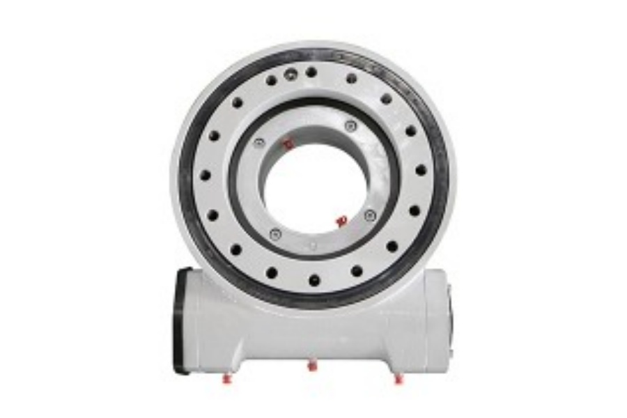
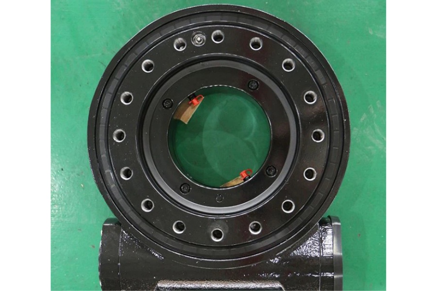
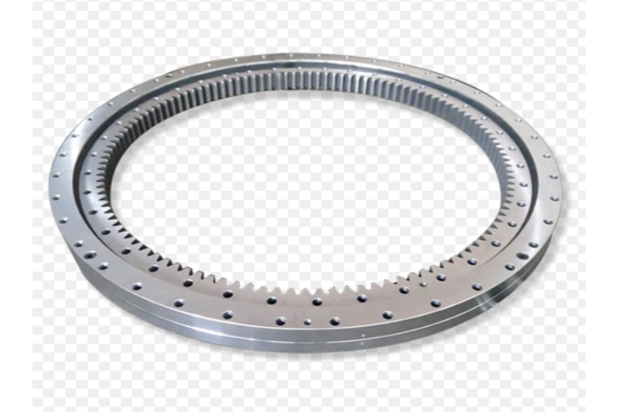
A slew drive is a gearbox mechanism that integrates a slewing ring bearing with a worm gear system to enable rotational movement under load. In solar tracking systems, slew drives play a crucial role by precisely orienting photovoltaic (PV) or concentrating solar power (CSP) panels toward the sun throughout the day, thereby maximizing energy generation.
Unlike fixed-mount solar panels, solar trackers equipped with slew drives can boost energy yields by 20–45%, depending on location and configuration. Selecting the correct slew drive for your tracking application is essential for performance, durability, and return on investment.
Types of Slew Drives for Solar Tracking
There are two common categories of slew drives used in solar applications:
Single-Axis Slew Drives
Function: Rotates panels from east to west.
Ideal For: Most ground-mount PV arrays and utility-scale projects.
LDB Models: SE Series, S Series
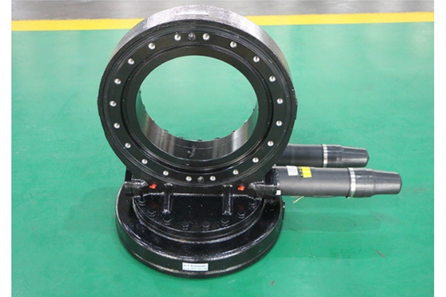
Dual-Axis Slew Drives
Function: Enables both horizontal and vertical movement.
Ideal For: CSP systems, concentrated PV, off-grid trackers, and regions with variable sunlight angles.
LDB Models: VE Series, HSE Series, HSE-2 Series
Key Selection Criteria
Torque Requirements
Slew drives must withstand wind loads and panel weight. Calculate holding torque and tracking torque under worst-case wind scenarios.
LDB provides torque charts for all models. For example, the HSE Series supports up to 25,000 Nm.
Rotation Range and Precision
Most solar applications require up to ±90° of rotation. Look for worm gears with low backlash for improved tracking accuracy.
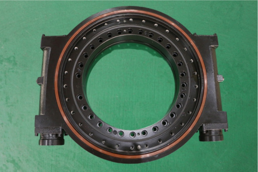
Dual-worm configurations (like SDE-PDE Series) can enhance torque and positioning precision.
Self-Locking Capability
Worm gear-based slew drives have a natural self-locking mechanism, preventing back-driving from wind forces—an important safety and energy-saving feature.
IP Rating and Weather Resistance
Outdoor solar trackers require drives rated at least IP66 to protect against dust, rain, and UV exposure.
LDB offers marine-grade coatings and stainless-steel options for desert or coastal climates.
Motor Integration
Choose between DC motors for off-grid systems or AC motors for grid-connected trackers.
LDB provides both electric and hydraulic drive compatibility.
LDB Slew Drive Product Recommendations for Solar
SE Series Slew Drive
Applications: Single-axis trackers
Torque: 1.2–80 kNm
Features: Compact design, easy mounting, weatherproof housing
HSE Series Slew Drive
Applications: Heavy-duty dual-axis systems
Torque: Up to 25,000 Nm
Features: High torque, precision tracking, anti-backlash
VE Series Slew Drive
Applications: Commercial dual-axis trackers
Torque: Medium-load dual-axis designs
Features: Reinforced gear structure, enhanced sealing
S Series Slew Drive
Applications: Light-duty single-axis systems
Features: Cost-effective, low noise, self-locking
Price Range for Solar Slew Drives
The price of a solar tracking slew drive depends on size, torque, and material finish. General estimates (USD):
| Product Line | Application Type | Price Range (USD) |
| SE Series | Small/medium trackers | $200 – $750 |
| VE Series | Dual-axis systems | $700 – $1200 |
| HSE Series | Utility-scale CSP | $1200 – $2500 |
| S Series | Entry-level systems | $150 – $400 |
LDB offers volume discounts for OEM integrators and solar EPC contractors.
Why LDB as Your Supplier and Manufacturer?
LDB is a globally recognized manufacturer and supplier of industrial slew drives, with specific expertise in solar energy systems. With over 15 years of experience, LDB has supported 500+ MW of solar tracker installations worldwide.
What sets LDB apart:
Over 10 models tailored for solar applications
CE, ISO, and SGS certifications
CAD design support and wind load simulation
Quick delivery and factory-direct pricing
On-site and remote engineering support
OEM Customization and Support
Need to match specific tracker specifications? LDB provides:
Custom flange dimensions
Modified gear ratios
Reinforced sealing and coatings
Motor bracket integration
For special orders, LDB’s engineering team can deliver technical drawings and samples within 15 working days.
Conclusion
A well-chosen slew drive can make or break a solar tracking project. By understanding torque demands, protection ratings, and motor control needs, integrators can ensure long-term reliability and maximum solar yield. With LDB’s wide product portfolio and customization services, your tracking systems will stay aligned with the sun—and your performance goals.
Contact LDB today to receive your tailored slew drive quote for your next solar energy project.