Choosing Between Single Row and Double Row Ball Slewing Bearings: A Practical Guide
What Are Single and Double Row Ball Slewing Bearings?
A slewing bearing is a specialized mechanical component designed to support heavy radial, axial, and moment loads while allowing smooth rotational movement. Slewing bearings are essential in construction equipment, renewable energy systems, and industrial automation.
Among the most common types are:
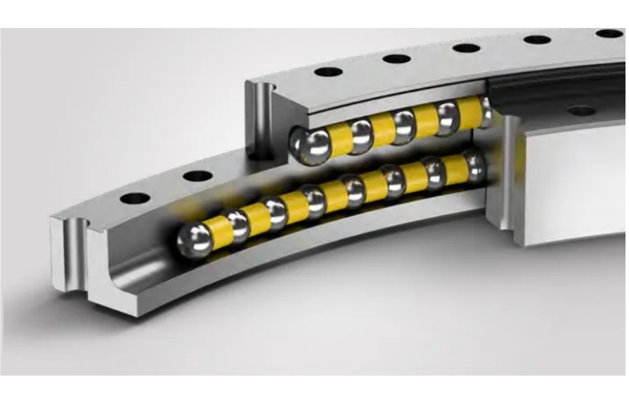
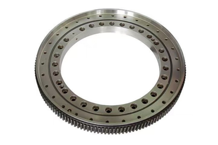
Single row four-point contact ball bearings, featuring one row of balls capable of handling axial and radial forces in both directions and overturning moments.
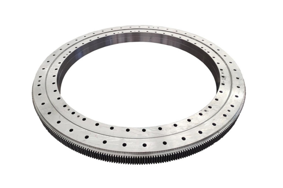
Double row ball slewing bearings, which incorporate two independent ball circuits to increase load capacity and improve stability.
Knowing when to choose a single or double row bearing is crucial to system performance, safety, and cost-effectiveness.
Single Row vs. Double Row Slewing Bearings: Design Overview
| Feature | Single Row Four-Point Contact | Double Row Ball |
| Ball Circuits | One | Two (typically with different diameters) |
| Load Capacity | Moderate | High (especially axial loads) |
| Outer Dimensions | Compact | Larger and heavier |
| Complexity | Simple design | More complex and costlier |
| Friction and Speed | Lower friction, higher speed | Higher resistance, slower operation |
| Common Applications | Cranes, turntables, robotics | Tower cranes, wind turbines, heavy loaders |
When to Choose a Single Row Slewing Bearing
Single row bearings are best suited for applications requiring:
Lower space consumption
Medium-duty performance
Higher rotational speed
Simpler installation and lower cost
LDB’s Recommended Product:
LDB-FQ Series – Four Point Contact Ball Slewing Bearing
Available in internal or external gear, or gearless versions
Outer diameter: 300mm–4500mm
Optimized for construction, loading equipment, and light rotary tables
When to Choose a Double Row Ball Slewing Bearing
Double row ball slewing bearings are preferred when:
The application requires higher axial and radial load capacity
The structure demands superior stability and torque support
Overturning moments are significant
LDB’s Recommended Product:
LDB-DB Series – Double Row Ball Slewing Bearing
Dual track design, with symmetric or asymmetric ball diameters
Customizable bolt hole patterns
Ideal for tower cranes, port machinery, and aerial work platforms
Application-Based Decision Making
| Application | Recommended Bearing Type |
| Excavators and Small Cranes | Single Row |
| Wind Turbine Yaw Bearings | Double Row |
| Robotics Turntables | Single Row |
| Port and Ship Cranes | Double Row |
| Compact Machinery | Single Row |
| High-load Civil Engineering | Double Row |
Load and Performance Comparison
Load Capacity
Double row bearings can support 30–50% more load compared to their single row counterparts of similar size, due to increased ball contact and distribution.
Moment Resistance
Double row designs offer superior resistance to tilting and torsional stress, ideal for applications involving significant moment loading.
Rotational Speed
Single row slewing bearings generally provide higher speed performance due to reduced friction.
LDB’s Slewing Bearing Engineering Advantages
As a global manufacturer and supplier, LDB offers a wide range of both single and double row slewing bearings with:
In-house gear heat treatment and grinding
Anti-rust coatings and sealing options
3D CAD drawings and simulation support
OEM customization (gear modules, hole patterns, clearance class)
All LDB slewing bearings undergo:
100% raceway hardening testing
Noise and clearance inspection
Serial number traceability
Optional CE/SGS/ISO certification
Price Comparison Guide
The price of a slewing bearing depends on diameter, structure, gear type, and load requirements.
| Type | Typical Diameter Range | Price Estimate (USD) |
| Single Row (LDB-FQ Series) | 400mm–2000mm | $150 – $800 |
| Double Row (LDB-DB Series) | 800mm–3000mm | $500 – $2000+ |
Bulk orders, OEM customization, and expedited delivery are available from LDB at competitive factory-direct pricing.
Why Choose LDB for Slewing Bearings?
20+ years of industry experience
Global export to 60+ countries
Full engineering and after-sales support
OEM manufacturing for major crane and turbine manufacturers
Fast prototyping and 3–4 week lead times for custom models
As both a manufacturer and supplier, LDB ensures quality, availability, and cost-efficiency.
Conclusion
Whether you need a compact and cost-effective rotary bearing or a high-capacity load-bearing solution, understanding the key differences between single and double row slewing bearings is essential.
LDB helps you make informed decisions with reliable products, tailored engineering, and end-to-end service. Contact us today to get expert guidance and pricing for your next slewing bearing application.