¿Cuáles son los métodos de instalación del impulsor de impulsión? Y precauciones de instalación

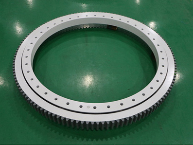
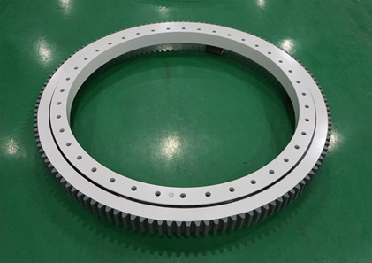
La transmisión por engranajes rectos es una transmisión rotativa. Debido a los diferentes tipos de dientes impulsores, se puede dividir en accionamiento rotativo de dientes rectos y accionamiento de dientes helicoidales, los cuales son mecanismos de transmisión de reducción de accionamiento rotativo de círculo completo que heredan la fuente de potencia de accionamiento. El artículo anterior ya ha introducido la diferencia entre la transmisión de engranajes rectos y la transmisión de giro. No lo presentaré en detalle aquí. Hoy, el fabricante de rodamientos de Lunda ofrecerá una breve introducción sobre los métodos de instalación de la transmisión por engranajes rectos. Espero que sea de ayuda para todos.

Método de instalación de la transmisión por engranajes rectos

1. Instalación fija con eje macizo

Este método de instalación consiste en conectar el eje de salida impulsado por el engranaje recto con la maquinaria metalúrgica a través de acoplamientos, ruedas dentadas, engranajes, poleas, etc., y el engranaje recto impulsa los pernos de anclaje inferiores para instalar firmemente el engranaje recto en la estructura. una base sólida y sin vibraciones. En la actualidad, la mayoría de los accionamientos de engranajes rectos pueden adoptar este método de instalación.

Para transmisiones de engranajes rectos grandes, se deben mecanizar orificios roscados en las patas del cuerpo para ajustar la posición de instalación con pernos de ajuste; Para la transmisión de engranajes rectos del mecanismo de abatimiento, también se deben usar pasadores para bloquear para evitar el movimiento durante la instalación.

2. Instalación flotante de un solo punto de eje hueco

Este método de instalación utiliza el eje de salida impulsado por el engranaje recto como un eje hueco y está conectado al eje de transmisión de la máquina de trabajo a través de un manguito de expansión. Todo el dispositivo de conducción, incluido el motor, el acoplamiento, el freno y el reductor, está instalado en el soporte del dispositivo de transmisión. Asiento y luego sostenido por una bisagra de bola o un cojinete.
El principio de instalación es que el punto de apoyo de la bisagra esférica se desvía del centro de gravedad del dispositivo de transmisión en una cierta distancia. En el estado de trabajo, el momento de flexión causado por la excentricidad del punto de apoyo se puede equilibrar con el momento de flexión causado por la carga del dispositivo de accionamiento. Por lo tanto, el eje de transmisión no se ve afectado por la teoría. Fuerza adicional.

3. Instalación de suspensión de eje hueco

En este método de instalación, el eje de salida impulsado por el engranaje recto y el eje de la maquinaria metalúrgica están conectados por un manguito de expansión, y el soporte se completa con el eje de salida y otra barra de torsión. Este método de instalación es relativamente simple, ahorra espacio en el piso y puede reducir el peso de toda la máquina, y es adecuado para dispositivos de transmisión que transmiten energía desde una dirección vertical.

La instalación de la transmisión por engranajes rectos es una tarea delicada y compleja con altos requisitos técnicos. Los procedimientos operativos y los datos de diseño deben observarse estrictamente durante el funcionamiento. La secuencia de instalación general es: nivelación y alineación del equipo, limpieza y montaje, ajuste y operación de prueba.

Después de comprender los métodos de instalación de transmisiones de engranajes rectos, los fabricantes de transmisiones de engranajes rectos introducirán algunas precauciones en la instalación de transmisiones de engranajes rectos. Espero que sea de ayuda para todos.

Precauciones para la instalación de la transmisión por engranajes rectos

WE Series Slewing Drive

1. Limpieza e inspección: limpie el eje de instalación de la transmisión de engranajes rectos antes de la instalación y el uso, y compruebe si el eje de instalación está magullado o sucio. Cuando la transmisión de engranajes rectos se instala de manera inclinada, asegúrese de que la posición alta del cojinete del eje del engranaje esté lubricada por el aceite para engranajes en la caja, y asegúrese de que el gas en la caja se pueda descargar desde la posición alta de la caja. .

2. Mantenga plana la interfaz de acoplamiento: al ensamblar la transmisión de engranajes rectos con el actuador y el motor primario, la brida de conexión debe limpiarse y pulirse para garantizar la planitud de la parte de conexión de la brida de conexión, para asegurarse de que esté nivelada, y todos los pernos de la circunferencia de la brida deben coincidir. , Fijación.

3. Mantenga el equilibrio: Los componentes de la transmisión ensamblados (acoplamientos, piñón) deben mantenerse en equilibrio de rotación, para no causar una fuerza radial o una fuerza axial inadmisibles. Normalmente se utiliza la rosca interna del dispositivo de montaje y el extremo del eje, y la parte de la transmisión se presiona con un perno; de lo contrario, se pueden dañar las partes internas de la transmisión de engranajes rectos.

4. Realice un buen trabajo de nivelación: La instalación de la transmisión de engranajes rectos debe fijarse rígidamente sobre una base horizontal sólida o un marco vertical, y la nivelación debe realizarse. Es necesario asegurarse de que la coaxialidad del motor primario, el acoplamiento, la transmisión de engranajes rectos y el actuador sea consistente, para evitar tensiones adicionales en los ejes de entrada y salida y los cojinetes del equipo y causar daños a la entrada y salida del equipo. ejes y cojinetes.

5. Controle el espacio del eje: la coaxialidad de las dos extensiones del eje conectadas debe controlarse dentro del rango de φ0,1 mm, y debe haber un espacio de 2-8 mm entre las caras de los extremos de las dos extensiones del eje. El valor del espacio depende del equipo específico conectado a la transmisión de engranajes rectos. Dependiendo de la situación, es necesario garantizar una capacidad de transferencia de carga suficiente y asegurarse de que los cojinetes accionados por el engranaje recto no estén sujetos a una fuerza axial adicional.

6. Agregue aceite para engranajes: el grado de aceite debe ser el valor de la transmisión de engranajes rectos, o se debe usar el aceite equivalente al aceite. Y la cantidad de aceite debe ser correcta, y cada transmisión de engranajes rectos tiene un letrero con el grado y la cantidad de aceite adjunto. El espejo de aceite es un espejo de visualización del nivel de aceite impulsado por el engranaje recto. En el lado de la transmisión de engranajes rectos, el nivel de aceite debe alcanzar las posiciones superior e inferior del centro del espejo de aceite al llenar el aceite.

Método de inyección de aceite y lubricación de transmisión por engranajes rectos

El efecto de lubricación tiene una gran influencia en la transmisión por engranajes rectos. Si las condiciones de lubricación no son buenas, el calor generado por la transmisión de engranajes rectos aumentará y su capacidad de carga disminuirá. Por lo tanto, el aceite lubricante y la cantidad de aceite deben seleccionarse correctamente para garantizar eficazmente el funcionamiento normal de la transmisión de engranajes rectos y prolongar su vida útil.

En circunstancias normales, el método de lubricación adopta la lubricación de la piscina de aceite y el enfriamiento natural; y para transmisión de engranajes rectos de alta potencia o potencia térmica insuficiente, se puede usar lubricación de aceite por circulación de presión o dispositivos de enfriamiento adicionales para enfriar.

En condiciones normales de funcionamiento, cuando la temperatura ambiente es de (0 ~ 35) ℃, o utilizando lubricación de aceite en circulación, elija aceite para engranajes industriales de servicio mediano 220 #; cuando la temperatura ambiente es (35 ~ 50) ℃, se recomienda seleccionar aceite para engranajes industriales de carga media 320 #. Además, la transmisión de engranajes rectos debe reemplazarse con aceite lubricante después de las primeras 400 horas de funcionamiento.

¿Cuáles son los métodos de instalación de la transmisión por engranajes rectos? Creo que ya lo sabes. Durante la instalación, puede elegir un método de instalación adecuado de acuerdo con las condiciones específicas de la máquina a la que se adapta la transmisión de engranajes rectos. Por supuesto, el fabricante de la transmisión de engranajes rectos ha introducido algunas precauciones durante el proceso de instalación. Arriba. Además, si tiene alguna pregunta sobre la instalación o el uso de otras transmisiones de engranajes rectos, puede llamarnos Longda Bearings y recibir sus llamadas.

What are the installation methods of the spur gear slewing drive? And installation precautions

Spur gear slewing drive is a rotary drive. Due to the different types of drive teeth, it can be divided into straight-tooth rotary drive and helical-tooth drive, both of which are full-circle rotary drive reduction transmission mechanisms that inherit the driving power source. The previous article has already introduced the difference between the spur gear drive and the slew drive. I will not introduce it in detail here. Today, the Lunda bearing manufacturer will give a brief introduction on the installation methods of the spur gear drive. I hope it will be helpful to everyone.

Installation method of spur gear drive

1. Fixed installation with solid shaft

This installation method is to connect the output shaft driven by the spur gear with the metallurgical machinery through couplings, sprockets, gears, pulleys, etc., and the spur gear drives the bottom anchor bolts to firmly install the spur gear drive on the structure On a solid, vibration-free foundation. At present, most spur gear drives can adopt this installation method.

For large spur gear drives, threaded holes should be machined on the body feet to adjust the installation position with adjusting bolts; for the spur gear drive of the luffing mechanism, pins should also be used for locking to prevent movement during installation .

2. Single-point floating installation of hollow shaft

This installation method uses the output shaft driven by the spur gear as a hollow shaft and is connected to the transmission shaft of the working machine through an expansion sleeve. The entire driving device, including the motor, coupling, brake, and reducer, is installed on the support of the transmission device. Seat, and then supported by a ball hinge or bearing.
The installation principle is that the bearing point of the spherical hinge deviates from the center of gravity of the transmission device by a certain distance. In the working state, the bending moment caused by the eccentricity of the support point can be balanced with the bending moment caused by the load of the driving device. Therefore, the transmission shaft is not affected by the theory. Additional force.

3. Hollow shaft suspension installation

In this installation method, the output shaft driven by the spur gear and the metallurgical machinery shaft are connected by an expansion sleeve, and the support is completed by the output shaft and another torsion rod. This installation method is relatively simple, saves floor space, and can reduce the weight of the whole machine, and is suitable for transmission devices that transmit power from a vertical direction.

Spur gear drive installation is a delicate and complex task with high technical requirements. The operating procedures and design data must be strictly observed during operation. The general installation sequence is: equipment leveling and alignment, cleaning and assembly, adjustment and trial operation.

After understanding the installation methods of spur gear drives, the spur gear drive manufacturers will introduce some precautions in the installation of spur gear drives. I hope it will be helpful to everyone.

Precautions for installation of spur gear drive

WE Series Slewing Drive

1. Cleaning and inspection: clean the spur gear drive installation shaft before installation and use, and check whether the installation shaft is bruised or dirty. When the spur gear drive is installed in an inclined manner, ensure that the high position of the gear shaft bearing is lubricated by the gear oil in the box, and ensure that the gas in the box can be discharged from the high position of the box.

2. Keep the mating interface flat: When assembling the spur gear drive with the actuator and the prime mover, the connecting flange should be cleaned and polished to ensure the flatness of the connecting part of the connecting flange, to ensure that it is flush, and all bolts on the flange circumference should be matched. , Fastening.

3. Keep balance: The assembled transmission components (couplings, sprocket) should be kept in rotation balance, so as not to cause impermissible radial force or axial force. The internal thread of the assembly fixture and the shaft end is usually used, and the transmission part is pressed in with a bolt, otherwise it may cause damage to the internal parts of the spur gear drive.

4. Do a good job of leveling: The spur gear drive installation must be rigidly fixed on a solid horizontal foundation or a vertical frame, and the leveling must be done. It is necessary to ensure that the coaxiality of the prime mover, coupling, spur gear drive, and actuator is consistent, so as to avoid additional stress on the input and output shafts and bearings of the equipment and cause damage to the equipment input and output shafts and bearings.

5. Control the shaft gap: the coaxiality of the two connected shaft extensions should be controlled within the range of φ0.1mm, and there should be a gap of 2-8mm between the end faces of the two shaft extensions. The value of the gap depends on the specific equipment connected to the spur gear drive. Depending on the situation, it is necessary to ensure sufficient load transfer capacity and to ensure that the bearings driven by the spur gear are not subject to additional axial force.

6. Add gear oil: The grade of oil should be the spur gear drive value, or the oil equivalent to the oil should be used. And the amount of oil must be correct, and each spur gear drive has a sign with the grade and quantity of oil attached. The oil mirror is a display mirror of the oil level driven by the spur gear. On the side of the spur gear drive, the oil level should reach the upper and lower positions of the middle of the oil mirror when filling oil.

Spur gear drive lubrication and oil injection method

The lubrication effect has a great influence on the spur gear drive. If the lubrication conditions are not good, the heat generated by the spur gear drive will increase and its carrying capacity will decrease. Therefore, the lubricating oil and the amount of oil must be selected correctly to effectively ensure the normal operation of the spur gear drive transmission and prolong its service life.

Under normal circumstances, the lubrication method adopts oil pool lubrication and natural cooling; and for high-power spur gear drive or insufficient thermal power, pressure circulating oil lubrication or additional cooling devices can be used for cooling.

Under normal operating conditions, when the ambient temperature is (0~35)℃, or using circulating oil lubrication, choose medium-duty industrial gear oil 220#; when the ambient temperature is (35~50)℃, it is recommended to select medium-load Industrial gear oil 320#. In addition, the spur gear drive should be replaced with lubricating oil after the first 400 hours of operation.

What are the installation methods of spur gear drive? I believe you already know it. During installation, you can choose a suitable installation method according to the specific conditions of the machine to which the spur gear drive is adapted. Of course, some precautions during the installation process have been introduced by the spur gear drive manufacturer. Up. In addition, if you have any questions about the installation or use of other spur gear drives, you can call us Longda Bearings, and welcome your calls.

Технологический процесс и способ обработки прямозубой ведущей шестерни

Мы часто говорим о зубчатом редукторе с цилиндрической зубчатой передачей. Он делится на прямозубую и косозубую шестерню. Его принцип работы – это в основном редуктор, который приводит во вращение коронную шестерню поворотного привода через ведущую шестерню. Итак, как много вы знаете о технологическом процессе обработки зубчатых колес для устройств, использующих зубчатые колеса для завершения работы по торможению? Следующие производители приводов познакомят вас с процессом обработки и методами обработки профиля зуба цилиндрических зубчатых колес.

Процесс обработки цилиндрической ведущей шестерни

Процесс обработки прямозубого ведущего зубчатого колеса включает в себя: ковку заготовки, нормализацию, токарную обработку, стружку зубчатого колеса, фрезерование зубчатых колес, формирование зубчатых колес, шлифовальную обработку, термообработку и обрезку. Конкретные процессы заключаются в следующем.

1. Поковка заготовки.

В последние годы горячая штамповка получила широкое распространение при обработке валов и подходит для изготовления заготовок для более сложных ступенчатых валов. Он отличается не только высокой точностью, небольшими припусками на последующую обработку и высокой производительностью.

Slewing Drive

2. Нормализация

Целью процесса нормализации является получение твердости, подходящей для последующего зубонарезания, чтобы уменьшить деформацию. Материал зубчатой стали обычно 20CrMnTi. На процесс влияют такие факторы, как оборудование, окружающая среда и скорость охлаждения заготовки, а разброс твердости велик.

3. Превращение

Чтобы удовлетворить требования к высокоточному позиционированию зубчатых колес, токарные станки с ЧПУ используются для обработки заготовок зубчатых колес для соблюдения требований к вертикальности торца, внешнего диаметра и диаметра отверстия, что может повысить точность заготовки зубчатого колеса и улучшить работу. эффективность.

4. Бритье

Технология шлифования радиальных зубчатых колес широко используется в производстве крупносерийных автомобильных зубчатых колес благодаря ее высокой эффективности, конструктивному профилю зуба и простоте реализации требований по модификации профиля зуба.

5. Прокатка и формовка

Обычные зубофрезерные станки и зубофрезерные станки по-прежнему широко используются для обработки зубчатых колес. Хотя его легко регулировать и обслуживать, эффективность производства невысока. Если создается большая мощность, требуется одновременное производство нескольких машин. С развитием технологии нанесения покрытия повторное покрытие после заточки варочных панелей и пластин стало очень удобным. Инструменты с покрытием могут значительно увеличить срок службы, как правило, более чем на 90%, эффективно сокращая количество смен инструмента. И время заточки дает существенное преимущество.

6. Шлифовка

В основном это обработка термообработанного внутреннего отверстия шестерни, торцевой поверхности, внешнего диаметра вала и других деталей для повышения точности размеров и уменьшения допусков формы и положения. Технология обработки зубчатых колес использует приспособление для позиционирования и зажима делительной окружности, которое может эффективно обеспечивать точность обработки зубчатой части и установочной базы, а также получать удовлетворительное качество продукции.

7. Термическая обработка.

Зубчатые колеса требуют науглероживания и закалки для обеспечения хороших механических свойств. Для продуктов, которые больше не нужно измельчать после нагрева, необходимо стабильное и надежное оборудование для термообработки.

8. Обрезка

Это проверка и очистка неровностей и заусенцев шестерен перед сборкой трансмиссии и зубчатой передачи для устранения аномального шума, вызываемого ими после сборки. Он завершается прослушиванием звука отдельной пары зацепления или наблюдением за отклонением зацепления на приборе для комплексного контроля.

SG-I Spur Gear Slewing Drive

Метод обработки цилиндрической ведущей шестерни

Выбор метода обработки профиля зуба цилиндрической зубчатой передачи в основном зависит от класса точности зубчатой передачи, формы конструкции, типа изготовления и условий производства. Для зубчатых колес различных классов точности обычно используются следующие методы обработки профиля зуба.

1. Шестерни ниже 8-го класса точности.

Зубчатые колеса из закаленной и отпущенной стали могут соответствовать требованиям при фрезеровании зубчатых колес или профилировании зубчатых колес. Для закаленных зубчатых колес может использоваться план обработки прокатки (придания формы) зуба-конец зуба обработка-закалка-исправление отверстия. Однако точность обработки профиля зуба перед закалкой должна быть повышена на один уровень.

SG-H Spur Gear Slewing Drive

2. Прецизионная шестерня 6-7 классов

Для закаленных зубчатых колес можно использовать: черновое фрезерование – мелкое фрезерование – обработка торца зуба – чистовая обработка – закалка – калибровка – эталонное хонингование.

3. Шестерни с точностью выше 5 класса.

Обычно используется: черновая зубофрезеровка – мелкая зубофрезеровка – обработка торцов зубьев – закалка – калибровка – стандартная черновая шлифовка зубчатых колес – тонкое шлифование зубчатых колес. Зубошлифование в настоящее время является высокоточным методом обработки профиля зуба с малым значением шероховатости поверхности, а точность может достигать 3-4.

Вышеупомянутое является введением о процессе обработки и методах обработки цилиндрической ведущей шестерни. Я надеюсь, что это поможет каждому получить определенное представление об обработке приводной шестерни.

Flujo de proceso y método de procesamiento del procesamiento de engranajes de accionamiento recto

La transmisión por engranajes rectos es una especie de reductor de engranajes que solemos decir. Se divide en engranajes rectos y engranajes helicoidales. Su principio de funcionamiento es principalmente un engranaje de reducción que impulsa la corona dentada del accionamiento giratorio para girar a través del engranaje de piñón. Entonces, ¿cuánto sabe sobre el proceso tecnológico de procesamiento de engranajes para dispositivos que usan engranajes para completar el trabajo de desaceleración? Los siguientes fabricantes de accionamientos le presentarán el proceso de procesamiento y los métodos de procesamiento de perfiles de dientes de los engranajes de accionamiento recto.

Proceso de mecanizado de engranajes impulsores rectos

El proceso de procesamiento del engranaje impulsor recto incluye: forjado en blanco, normalización, procesamiento de torneado, afeitado de engranajes, tallado, modelado de engranajes, procesamiento de rectificado, tratamiento térmico y recorte. Los procesos específicos son los siguientes.

1. Palanquilla de forja

En los últimos años, la forja en caliente se ha promovido ampliamente en el procesamiento de ejes y es adecuada para hacer piezas en bruto para ejes escalonados más complejos. No solo tiene alta precisión, pequeñas tolerancias de mecanizado posterior y alta eficiencia de producción.

Slewing Drive

2. Normalización

El propósito del proceso de normalización es obtener una dureza adecuada para el posterior corte de engranajes para reducir la deformación. El material del acero para engranajes utilizado suele ser 20CrMnTi. El proceso se ve afectado por factores como el equipo, el entorno y la velocidad de enfriamiento de la pieza de trabajo, y la dispersión de la dureza es grande.

3. Girando

Para cumplir con los requisitos de posicionamiento de alta precisión de los engranajes, los tornos CNC se utilizan para el procesamiento de piezas en bruto de engranajes para mantener los requisitos de verticalidad de la cara del extremo, el diámetro exterior y el diámetro del orificio, lo que puede mejorar la precisión de la pieza en bruto del engranaje y mejorar el trabajo eficiencia.

4. Afeitado

La tecnología de afeitado de engranajes radiales se utiliza ampliamente en la producción de engranajes de automóviles de gran volumen debido a su alta eficiencia, diseño de perfil de diente y fácil realización de los requisitos de modificación del perfil de diente.

5. Enrollar y dar forma

Las máquinas de tallado de engranajes comunes y las máquinas de conformado de engranajes todavía se utilizan ampliamente para procesar engranajes. Aunque es fácil de ajustar y mantener, la eficiencia de producción es baja. Si se completa una gran capacidad, se requieren varias máquinas para producir al mismo tiempo. Con el desarrollo de la tecnología de recubrimiento, volver a recubrir después del afilado de placas e insertos es muy conveniente. Las herramientas revestidas pueden aumentar significativamente la vida útil, generalmente en más del 90%, reduciendo efectivamente el número de cambios de herramienta y el tiempo de afilado, el beneficio es significativo.

6. Molienda

Es principalmente para terminar el orificio interior del engranaje tratado térmicamente, la cara del extremo, el diámetro exterior del eje y otras partes para mejorar la precisión dimensional y reducir la tolerancia de forma y posición. La tecnología de procesamiento de engranajes adopta el accesorio de círculo de paso para colocar y sujetar, lo que puede garantizar de manera efectiva la precisión del procesamiento de la parte del diente y el punto de referencia de instalación, y obtener una calidad de producto satisfactoria.

7. Tratamiento térmico

Los engranajes requieren carburación y enfriamiento para asegurar buenas propiedades mecánicas. Para productos que ya no necesitan ser molidos después de ser calentados, es esencial un equipo de tratamiento térmico estable y confiable.

8. Recorte

Esta es la inspección y limpieza de los golpes y rebabas de los engranajes antes del ensamblaje de la transmisión y la transmisión por engranajes para eliminar el ruido anormal causado por ellos después del ensamblaje. Se completa escuchando el sonido de un solo par de mallas u observando la desviación de las mallas en un instrumento de inspección integral.

SG-I Spur Gear Slewing Drive

Método de mecanizado del engranaje impulsor de dientes rectos

La elección del método de procesamiento del perfil del diente de accionamiento recto depende principalmente del grado de precisión del engranaje, la forma estructural, el tipo de producción y las condiciones de producción. Para engranajes de diferentes grados de precisión, los métodos de procesamiento de perfiles de dientes comúnmente utilizados son los siguientes.

1. Marchas por debajo de la precisión de grado 8

Los engranajes endurecidos y revenido pueden cumplir los requisitos con tallado o modelado de engranajes. Para engranajes endurecidos, se puede utilizar un plan de mecanizado de laminación (conformación) de dientes, procesamiento de extremos de dientes, enfriamiento y orificio de corrección. Sin embargo, la precisión del mecanizado del perfil del diente debe mejorarse en un nivel antes del temple.

SG-H Spur Gear Slewing Drive

2. Engranaje de precisión de 6-7 grados

Para engranajes templados, se puede utilizar lo siguiente: tallado en bruto-tallado fino-mecanizado de extremos de dientes-raspado fino-endurecimiento de la superficie-calibración de referencia-bruñido.

3. Engranajes con precisión superior al grado 5

Usado generalmente: tallado de engranajes ásperos-tallado de engranajes finos-mecanizado de extremos de dientes-templado-calibración estándar-engranaje de molienda rugosa-engranaje de molienda fina El rectificado de engranajes es actualmente un método de mecanizado de alta precisión en el mecanizado de perfiles de dientes con un valor de rugosidad superficial pequeño, y la precisión puede ser tan alta como 3-4.

Lo anterior es la introducción sobre el proceso de procesamiento y los métodos de procesamiento del engranaje impulsor de dientes rectos. Espero que pueda ayudar a todos a tener una cierta comprensión del procesamiento del engranaje impulsor.

Process flow and processing method of spur drive gear processing

Spur gear drive is a kind of gear reducer we often say. It is divided into spur gear and helical gear. Its working principle is mainly a reduction gear that drives the ring gear of the rotary drive to rotate through the pinion gear. So how much do you know about the technological process of gear processing for devices that use gears to complete the deceleration work? The following drive manufacturers will introduce to you the processing process and tooth profile processing methods of spur drive gears.

Machining process of spur drive gear

The processing process of spur drive gear includes: forging blank, normalizing, turning processing, gear shaving, hobbing, gear shaping, grinding processing, heat treatment, and trimming. The specific processes are as follows.

1. Forging billet

In recent years, hot die forging has been widely promoted in shaft processing, and is suitable for making blanks for more complex stepped shafts. It not only has high precision, small subsequent machining allowances, and high production efficiency.

Slewing Drive

2. Normalizing

The purpose of the normalizing process is to obtain a hardness suitable for subsequent gear cutting to reduce deformation. The material of the gear steel used is usually 20CrMnTi. The process is affected by factors such as equipment, environment, and workpiece cooling rate, and the hardness dispersion is large.

3. Turning

In order to meet the high-precision positioning requirements of gears, CNC lathes are used for gear blank processing to maintain the verticality requirements of the end face, outer diameter, and bore diameter, which can improve the precision of the gear blank and improve work efficiency.

4. Shaving

Radial gear shaving technology is widely used in the production of high-volume automobile gears due to its high efficiency, design tooth profile, and easy realization of tooth profile modification requirements.

5. Rolling and shaping

Common gear hobbing machines and gear shaping machines are still widely used for processing gears. Although it is easy to adjust and maintain, the production efficiency is low. If a large capacity is completed, multiple machines are required to produce at the same time. With the development of coating technology, the re-coating after sharpening of hobs and inserts is very convenient. Coated tools can significantly increase the service life, generally by more than 90%, effectively reducing the number of tool changes And sharpening time, the benefit is significant.

6. Grinding

It is mainly to finish the heat-treated gear inner hole, end face, shaft outer diameter and other parts to improve the dimensional accuracy and reduce the form and position tolerance. The gear processing technology adopts the pitch circle fixture to position and clamp, which can effectively ensure the processing accuracy of the tooth part and the installation datum, and obtain satisfactory product quality.

7. Heat treatment

Gears require carburizing and quenching to ensure good mechanical properties. For products that no longer need to be ground after being heated, stable and reliable heat treatment equipment is essential.

8. Trimming

This is the inspection and cleaning of the bumps and burrs of the gears before assembly of the transmission and gear drive to eliminate the abnormal noise caused by them after assembly. It is completed by listening to the sound of a single pair of meshing or observing the meshing deviation on a comprehensive inspection instrument.

SG-I Spur Gear Slewing Drive

Machining method of spur drive gear

The choice of spur drive tooth profile processing method mainly depends on the gear’s accuracy grade, structural shape, production type and production conditions. For gears of different accuracy grades, the commonly used tooth profile processing methods are as follows.

1. Gears below grade 8 accuracy

Hardened and tempered gears can meet the requirements with gear hobbing or gear shaping. For hardened gears, a machining plan of rolling (shaping) teeth-tooth end processing-quenching-correction hole can be used. However, the machining accuracy of the tooth profile should be improved by one level before quenching.

SG-H Spur Gear Slewing Drive

2. 6-7 grade precision gear

For hardened gears, the following can be used: rough hobbing-fine hobbing-tooth end machining-fine shaving-surface hardening-calibration reference-honing.

3. Gears with accuracy above grade 5

Generally used: rough gear hobbing-fine gear hobbing-tooth end machining-quenching-calibration standard-rough grinding gear-fine grinding gear. Gear grinding is currently a high-precision machining method in tooth profile machining with a small surface roughness value, and the accuracy can be as high as 3-4.

The above is the introduction about the processing process and processing methods of the spur drive gear. I hope it can help everyone to have a certain understanding of the processing of the drive gear.

Каковы процессы ремонта поворотных подшипников?

Опорно-поворотный подшипник также называют поворотным кольцом. Это новый тип механических деталей. Оно состоит из внутреннего и внешнего колец, тел качения и т. Д. Опорно-поворотное устройство – это крупногабаритный подшипник, способный выдерживать большие нагрузки и одновременно выдерживать больший осевой и больший диаметр. Подшипник для нагрузки и опрокидывающего момента.

Как правило, он широко используется в промышленности, и эффект от использования очень хороший. Применение поворотных подшипников является особенным, и они должны работать в условиях непрерывных ударов, вибрации и перегрузок. Таким образом, контроль технических параметров производства в процессе производства продукта также является более строгим, с высокой прочностью склеивания, без осыпания, без твердых пятен, высокой отделкой поверхности и регулируемой твердостью. Однако повреждение по-прежнему неизбежно, что требует специальных методов ремонта, чтобы обеспечить гибкость последующего применения поворотного кольца.

Процесс ремонта поворотного подшипника

Slewing Bearings

1. Метод низкотемпературного железного покрытия

Нанесение покрытия из низкотемпературного железа – широко используемый метод ремонта деталей вала в промышленности, и он уже давно применяется в других отраслях механического обслуживания. Низкотемпературное железное покрытие – это технология нанесения гальванического покрытия с высокой скоростью нанесения покрытия на железо. Одноразовое железное покрытие имеет большую толщину, относительно зрелый процесс и высокую эффективность производства. Подходит для ремонта поверхности валов или деталей трансмиссии сельскохозяйственной техники.

2. Метод термического напыления.

Метод термического напыления в основном использует высокоскоростной воздушный поток для распыления расплавленного металлического материала на поверхность частично изношенных деталей, а затем размер может быть восстановлен после обработки. Технология термического напыления включает в себя множество методов, таких как напыление пламенем, электрическое напыление и плазменное напыление. Дополнительные материалы для распыления часто лучше, чем сырье, поэтому после ремонта поворотного подшипника их детали с точки зрения износостойкости и коррозионной стойкости значительно улучшились.

ceshi

3. Метод наплавки.

Метод наплавки заключается в использовании процесса сварки для наплавки слоя сварочного материала на изношенные части детали с последующим восстановлением исходного размера детали путем механической обработки. В процессе наплавки можно добиться различных эффектов ремонта материала за счет выбора сварочных стержней или проволоки. Этот процесс имеет преимущества высокой прочности материала после ремонта и более высокой скорости ремонта, а также подходит для ремонта деталей с большим износом.

Характеристики правильно отремонтированного подшипника эквивалентны характеристикам нового подшипника, и все параметры, такие как зазор, могут соответствовать требованиям использования. Чтобы выбрать правильный план ремонта, важно понимать и определять степень повреждения. Ремонт подшипников требует длительного технического накопления и исчерпывающего хранения исходных данных. Профессионально обученный персонал может решить, нуждается ли подшипник в ремонте. Своевременные плановые осмотры, профилактическое обслуживание и анализ вибрации могут определить подходящее время ремонта во времени, чтобы помочь компаниям экономично отремонтировать поврежденные подшипники.

¿Cuáles son los procesos de reparación para los cojinetes de giro?

El cojinete de giro también se llama  anillo de giro  . Es un nuevo tipo de piezas mecánicas. Está compuesto por anillos interiores y exteriores, elementos rodantes, etc. El anillo giratorio es un rodamiento a gran escala que puede soportar cargas amplias y puede soportar axiales y diámetros mayores al mismo tiempo. Cojinete para carga y momento de vuelco.

Generalmente, se usa ampliamente en la industria y el efecto de uso es muy bueno. La aplicación de los cojinetes giratorios es especial y debe funcionar bajo golpes, vibraciones y sobrecargas continuas. Por lo tanto, el control de los parámetros técnicos de producción en el proceso de fabricación del producto también es más riguroso, con alta fuerza de unión, sin desprendimiento, sin puntos duros, alto acabado superficial y dureza ajustable. Sin embargo, el daño sigue siendo inevitable, lo que requiere técnicas de reparación especiales para garantizar la flexibilidad de la aplicación posterior del anillo giratorio.

Proceso de reparación de rodamiento giratorio

Cojinetes giratorios

1. Método de enchapado de hierro a baja temperatura

El enchapado de hierro a baja temperatura es un método comúnmente utilizado para reparar piezas de ejes en la industria, y tiene una larga historia de aplicación en otras industrias de mantenimiento mecánico. El enchapado de hierro a baja temperatura es una tecnología de galvanoplastia con una velocidad de enchapado de hierro rápido. El enchapado de hierro de una sola vez tiene un gran espesor, un proceso relativamente maduro y una alta eficiencia de producción. Es adecuado para reparar la superficie de ejes o piezas de transmisión de maquinaria agrícola.

2. Método de pulverización térmica

El método de pulverización térmica utiliza principalmente un flujo de aire de alta velocidad para pulverizar material metálico fundido en la superficie de las piezas parcialmente desgastadas, y luego se puede restaurar el tamaño después del procesamiento. La tecnología de pulverización térmica incluye muchos métodos, como la pulverización por llama, la pulverización eléctrica y la pulverización de plasma. Los materiales adicionales para la pulverización suelen ser mejores que las materias primas, por lo que después de reparar el cojinete de giro, las piezas en términos de resistencia al desgaste y a la corrosión se han mejorado considerablemente.

ceshi

3. Método de revestimiento

El método de revestimiento consiste en utilizar el proceso de soldadura para revestir una capa de material de soldadura en las partes desgastadas de la pieza y luego restaurar el tamaño original de la pieza mediante un procesamiento mecánico. El proceso de revestimiento puede lograr diferentes efectos de reparación de materiales mediante la selección de varillas o alambres de soldadura. El proceso tiene las ventajas de una alta resistencia del material después de la reparación y una mayor velocidad de reparación, y es adecuado para reparar piezas con mayor desgaste.

El rendimiento del rodamiento correctamente reparado es equivalente al nuevo rodamiento, y todos los parámetros, como el juego, pueden cumplir con los requisitos de uso. Es importante comprender e identificar el grado de daño para elegir el plan de reparación correcto. La reparación de rodamientos requiere una acumulación técnica a largo plazo y un almacenamiento de datos básicos completos. El personal capacitado profesionalmente puede juzgar si es necesario reparar el rodamiento. Las inspecciones de rutina oportunas, el mantenimiento preventivo y el análisis de vibraciones pueden captar el tiempo de reparación adecuado a tiempo, para ayudar a las empresas a reparar de forma económica los rodamientos dañados.

What are the repair processes for slewing bearings?

The slewing bearing is also called the slewing ring. It is a new type of mechanical parts. It is composed of inner and outer rings, rolling elements, etc. The slewing ring is a large-scale bearing that can withstand comprehensive loads, and can withstand larger axial and diameter at the same time. Bearing for load and overturning moment.

Generally, it is widely used in industry, and the effect of use is very good. The application of slewing bearings is special, and it must be operated under continuous shock, vibration, and overload. Therefore, the control of production technical parameters in the product manufacturing process is also It is more rigorous, with high bonding strength, no shedding, no hard spots, high surface finish, and adjustable hardness. However, damage is still inevitable, which requires special repair techniques to ensure the flexibility of the later application of the slewing ring.

Repair process of slewing bearing

Slewing Bearings

1. Low temperature iron plating method

Low-temperature iron plating is a commonly used method for repairing shaft parts in the industry, and it has a long history of application in other mechanical maintenance industries. Low-temperature iron plating is an electroplating technology with a fast iron plating speed. The one-time iron plating has a large thickness, a relatively mature process and high production efficiency. It is suitable for repairing the surface of agricultural machinery transmission shafts or parts.

2. Thermal spraying method

Thermal spraying method mainly uses high-speed airflow to spray molten metal material on the surface of partially worn parts, and then the size can be restored after processing. Thermal spraying technology includes many methods such as flame spraying, electric spraying and plasma spraying. The additional materials for spraying are often better than the raw materials, so after the slewing bearing is repaired, the parts in terms of wear resistance and corrosion resistance have been greatly improved.

ceshi

3. Surfacing method

The surfacing method is to use the welding process to surfacing a layer of welding material on the worn parts of the part, and then restore the original matching size of the part through mechanical processing. The surfacing process can achieve different material repair effects through the selection of welding rods or wires. The process has the advantages of high material strength after repair and faster repair speed, and is suitable for repairing parts with greater wear.

The performance of the correctly repaired bearing is equivalent to that of the new bearing, and all parameters such as clearance can meet the requirements of use. It is important to understand and identify the degree of damage to choose the correct repair plan. Bearing repair requires long-term technical accumulation and comprehensive basic data storage. Professionally trained personnel can judge whether the bearing needs to be repaired. Timely routine inspections, preventive maintenance and vibration analysis can grasp the appropriate repair time in time, so as to help companies economically repair damaged bearings.

Инвентаризация общих причин неисправностей поворотных подшипников, анализ и решения

Подшипники часто выходят из строя во время работы, поэтому не нужно суетиться. В случае отказа – ключ к определению причины повреждения и устранению его. Сегодня редактор подсчитал некоторые распространенные причины поломки поворотного подшипника, анализ и решения.

Трещины дефекты

Явление неисправности: частичные зазубрины и трещины.

1. Причина неисправности

① Чрезмерная ударная нагрузка; ② Чрезмерное вмешательство; ③Большой пилинг; ④ трещины от трения; ⑤Недостаточная точность установки стороны (слишком большой угол закругления); ⑥Недостаточное использование (для вставки крупных посторонних предметов используется медный молоток).

2. Решения

①Проверьте условия использования; ②Установите соответствующие помехи и проверьте материалы; ③Улучшать методы установки и использования; ④Предотвратить образование трещин от трения (проверить смазку); ⑤ Проверьте конструкцию подшипника.

Вращение поворотного подшипника не гибкое

Явление неисправности: нагрев подшипника, дрожание, заедание.

1. Причина неисправности

①Зазор слишком мал (включая зазор деформированной детали); ②Недостаточная смазка или неподходящий смазочный материал; ③ Чрезмерная нагрузка (чрезмерная предварительная нагрузка); ④Валик перекошен.

Slewing Bearings

2. Решения

①Установить правильный зазор (увеличить зазор); ②Проверьте тип смазки, чтобы убедиться в количестве впрыска; ③Проверьте условия использования; ④Предотвращение ошибок позиционирования; ⑤ Проверьте конструкцию подшипника (включая нагрев подшипника).

Слой твердости отваливается

Явление проблемы: беговая поверхность отслаивается, и после отслаивания она явно выпуклая и вогнутая.

1. Причина

①Неправильное использование из-за чрезмерной нагрузки; ②Неплохая установка; ③Низкая точность вала или подшипниковой коробки; ④Слишком маленький клиренс; ⑤Проникновение посторонних предметов; ⑥ ржавчина; ⑦ Снижение жесткости из-за аномально высокой температуры

2. Решения

①Переизучить условия эксплуатации; ②Повторно выберите подшипник; ③Пересмотреть зазор; ④Проверьте точность обработки вала и корпуса подшипника; ⑤Исследуйте конструкцию подшипника; ⑥Проверьте способ установки; ⑦Проверьте смазку и метод смазки.

Slewing Bearings

Царапины и заеды

Явление неисправности: шероховатая поверхность, сопровождающаяся микро растворением; царапины между кольцевыми ребрами и торцами роликов называются заедами

1. Причина

① Плохая смазка; ② Попадание посторонних предметов; ③ Прогиб ролика из-за наклона подшипника; ④ Разрушение масла на поверхности ребра из-за большой осевой нагрузки; ④ Шероховатость поверхности; ⑤ Большой подвижный элемент скольжения.

2. Решения

①Переучить смазочные материалы и методы смазки; ②Проверьте условия использования; ③ Установите соответствующий предварительный натяг; ④Повышение герметичности; ⑤ Используйте подшипник как обычно.

Клетка повреждена

Явление неисправности: ослабленная или сломанная заклепка, сломанная клетка.

1. Причина

① Чрезмерная крутящая нагрузка; ② Высокая скорость вращения или частая смена скорости; ③ Плохая смазка; ④Захваченные посторонние предметы; ⑤Большая вибрация; ⑥Независимая установка (установка в наклонном состоянии); ⑦ Ненормальное повышение температуры (полимерная клетка).

2. Решения

① Проверить условия эксплуатации; ② Проверить условия смазки; ③Подробнее изучить выбор клетки; ④Обратите внимание на использование подшипников; ⑤Изучите жесткость вала и подшипниковой коробки.

Ржавая коррозия на поверхности поворотного подшипника.

Явление неисправности: часть или вся поверхность покрыта ржавчиной, и она покрыта ржавчиной в виде шага тел качения.

1. Причина

① Плохое состояние хранения; ②Неправильная упаковка; ③ Недостаточное количество ингибитора ржавчины; ④Проникновение влаги, раствора кислоты и др .; ⑤ Удерживайте подшипник рукой.

2. Решения

① Предотвратить ржавчину при хранении; ②Повышение герметичности; ③ Регулярно проверяйте смазочное масло; ④Обратите внимание на использование подшипников.

Истирание

Явление неисправности: на сопрягаемой поверхности образуются частицы износа красного цвета ржавчины.

1. Причина

①Недостаточное вмешательство; ②Малый угол поворота подшипника; ③Недостаточная смазка (или в несмазанном состоянии); ④Нестабильная нагрузка; ⑤Вибрация при транспортировке.

2. Решения

①Проверьте состояние натяга и смазочного покрытия; ②Внутреннее и внешнее кольца упаковываются отдельно во время транспортировки, и если они не могут быть разделены, применяется предварительное давление; ③Выберите смазку; ④Выберите подшипник.

Slewing Bearings

Носить

Явление: поверхностный износ, приводящий к изменению размеров, часто сопровождающийся истиранием и следами износа.

1. Причина

① Смазка смешана с посторонними предметами; ②Слабая смазка; ③Валик перекошен.

2. Решения

①Проверьте смазочный материал и метод смазки; ②Повышение герметичности; ③ Предотвратить ошибку позиционирования.

Ушибы вдавливания

Явление неисправности: ямы на поверхности, вызванные застрявшими твердыми посторонними предметами, или удары и царапины, вызванные установкой

1. Причина

①Проникновение твердых инородных тел; ② Вставьте очищающий лист; ③Удар и падение из-за неправильной установки; ④Установить в наклонном состоянии.

2. Решения

①Улучшить методы установки и использования; ② Не допускать попадания посторонних предметов; ③Если это вызвано металлическими листами, проверьте другие детали.

Электрическая эрозия

Устранить это явление: поверхность качения имеет ямчатую ямку, а дальнейшее развитие имеет форму волновой пластины.

1. Причина

Поверхность качения находится под напряжением.

2. Решения

Сделать токовый перепускной клапан; примите меры по изоляции, чтобы ток не проходил через внутреннюю часть подшипника.

Выше приведено объяснение распространенного явления отказа при повреждении опорно-поворотного подшипника, анализ причин и меры по их устранению. Я надеюсь, что все будут полезны после прочтения. Анализ форм повреждений и отказов поворотного подшипника может предоставить подробную справочную информацию по конструкции и выбору подшипника, а затем улучшить конструкцию, рационально выбрать подшипник, обеспечить полный люфт функции подшипника, повысить экономические выгоды и увеличить срок службы.

El inventario de la falla de daños por cojinetes de giro común causa análisis y soluciones

Es común que los rodamientos fallen durante el funcionamiento, por lo que no hay necesidad de hacer un escándalo. En el caso de una falla, la clave para determinar la causa del daño y manejarla Hoy, el editor ha contado algunos análisis y soluciones comunes de fallas de daños en los rodamientos giratorios .

 Defectos de grietas

Fenómeno de problema: parcialmente mellado y agrietado

1. La causa del fallo

① Carga de impacto excesiva; ② Interferencia excesiva; ③ Gran descamación; ④ Grietas por fricción; ⑤Pobre precisión del lado de instalación (esquina redonda demasiado grande); ⑥ Mal uso (se usa un martillo de cobre para insertar objetos extraños grandes).

2. Soluciones

①Check the conditions of use; ②Set appropriate interference and check materials; ③Improve installation and use methods; ④Prevent friction cracks (check lubricant); ⑤Check the design around the bearing.

Rotation of slewing bearing is not flexible

Trouble phenomenon: bearing heating, jitter, stuck.

1. The cause of the failure

①The clearance is too small (including the clearance of the deformed part); ②Insufficient lubrication or improper lubricant; ③Excessive load (excessive preload); ④The roller is skewed.

Cojinetes giratorios

2. Solutions

①Set proper clearance (increase the clearance); ②Check the type of lubricant to ensure the amount of injection; ③Check the conditions of use; ④Prevent positioning errors; ⑤Check the design around the bearing (including heating of the bearing).

The hardness layer falls off

Trouble phenomenon: the running surface is peeled off, and it is obviously convex and concave after peeling off.

1. Reason

①Improper use due to excessive load; ②Poor installation; ③Poor precision of shaft or bearing box; ④Too small clearance; ⑤Intrusion of foreign matter; ⑥rusting; ⑦Hardness reduction caused by abnormal high temperature

2. Solutions

①Re-study the operating conditions; ②Re-select the bearing; ③Reconsider the clearance; ④Check the machining accuracy of the shaft and the bearing housing; ⑤Research the design around the bearing; ⑥Check the installation method; ⑦Check the lubricant and lubrication method.

Cojinetes giratorios

Scratches and jams

Trouble phenomenon: rough surface, accompanied by micro-dissolving; scratches between ring ribs and roller end faces are called jams

1. Reason

① Poor lubrication; ② Foreign matter intrusion; ③ Roller deflection caused by bearing tilt; ④ Oil breaking on rib surface caused by large axial load; ④ Surface roughness; ⑤ Large rolling element sliding.

2. Solutions

①Re-study lubricants and lubrication methods; ②Check the conditions of use; ③Set appropriate preload; ④Strengthen the sealing performance; ⑤Use the bearing normally.

The cage is damaged

Trouble phenomenon: loose or broken rivet, broken cage.

1. Reason

①Excessive torque load; ②High-speed rotation or frequent speed changes; ③Poor lubrication; ④Entrapped foreign objects; ⑤Large vibration; ⑥Poor installation (installation in tilted state); ⑦Abnormal temperature rise (resin cage).

2. Solutions

①Check the operating conditions; ②Check the lubrication conditions; ③Re-study the selection of the cage; ④Pay attention to the use of bearings; ⑤Study the rigidity of the shaft and the bearing box.

Rusty corrosion on the surface of the slewing bearing

Trouble phenomenon: Part or all of the surface is rusty, and it is rusty in the form of pitch of rolling elements.

1. Reason

①Poor storage condition; ②Improper packaging; ③Insufficient rust inhibitor; ④Intrusion of moisture, acid solution, etc.; ⑤Hold the bearing directly by hand.

2. Solutions

①Prevent rust during storage; ②Strengthen the sealing performance; ③Check the lubricating oil regularly; ④Pay attention to the use of bearings.

Abrasion

Trouble phenomenon: red rust-colored wear particles are produced on the mating surface.

1. Reason

①Insufficient interference; ②Small bearing swing angle; ③Insufficient lubrication (or in a non-lubricated state); ④Unstable load; ⑤Vibration during transportation.

2. Solutions

①Check the interference and lubricant coating status; ②The inner and outer rings are packaged separately during transportation, and pre-pressure is applied if they cannot be separated; ③Reselect the lubricant; ④Reselect the bearing.

Cojinetes giratorios

Wear

Phenomenon: Surface wear, resulting in dimensional changes, often accompanied by abrasion and wear marks

1. Reason

①The lubricant is mixed with foreign matter; ②The lubrication is poor; ③The roller is skewed.

2. Solutions

①Check lubricant and lubrication method; ②Strengthen sealing performance; ③Prevent positioning error.

Indentation bruises

Trouble phenomenon: surface pits caused by stuck solid foreign objects or impact and scratches caused by installation

1. Reason

①Intrusion of solid foreign matter; ②Insert the peeling sheet; ③Shock and fall off caused by poor installation; ④Install in an inclined state.

2. Solutions

①Improve the installation and use methods; ②Prevent foreign matter from entering; ③If it is caused by metal sheets, check other parts.

Electric erosion

Resolve the phenomenon: the rolling surface has a pit-like pit, and the further development is in a wave plate shape.

1. Reason

The rolling surface is energized.

2. Solutions

Make a current bypass valve; take insulation measures to prevent current from passing through the inside of the bearing.

Lo anterior es la explicación del fenómeno común de falla por daño del cojinete giratorio, el análisis de la razón y las medidas de solución. Espero que todos sean de ayuda después de leerlo. El análisis de las formas de daño y falla del rodamiento giratorio puede proporcionar una referencia detallada para el diseño y la selección del rodamiento, y luego mejorar el diseño, seleccionar racionalmente el rodamiento, dar pleno juego a la función del rodamiento, aumentar los beneficios económicos y aumentar la vida útil.